6
Terminal unit
Leave at least 80 mm at the sides and rear to
permit the checking and maintenance.
1. Fix the hanger on a table with four tapping
screws.
2. Attach connectors from external equipment
to bottom panel.
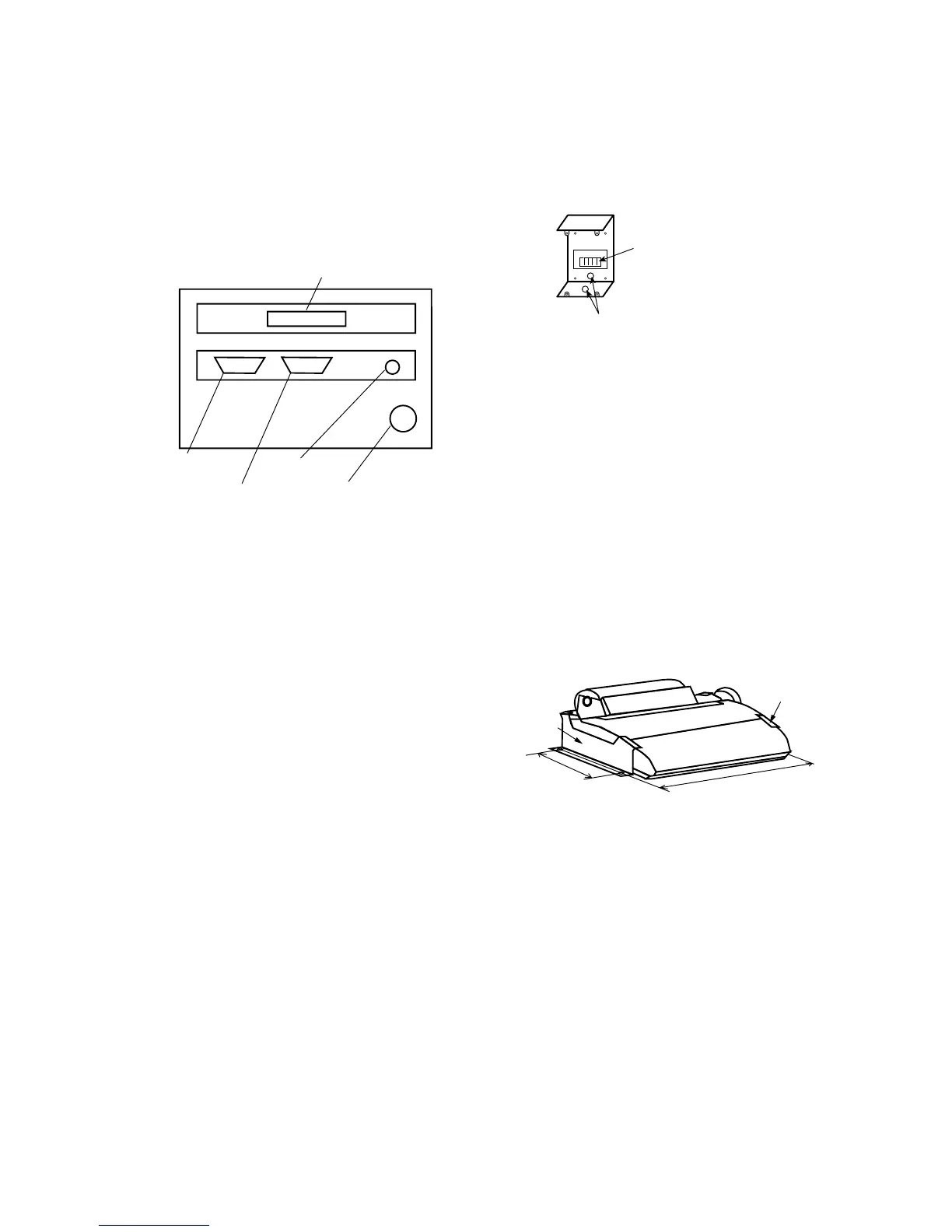
PRINTER
COM1
COM2
K-BOARD
24VDC
Keyboard
Printer
Ship’s Mains 24VDC
Not used
Communication
Unit
Figure 3-10 IB-581, bottom view
3. Screw knobs in terminal unit and set the ter-
minal unit to the hanger.
4. Adjust the display screen so it can be easily
viewed. Tighten knobs.
Keyboard
1. Attach the four “hook loop fasteners 3”
(small) to the bottom of the keyboard.
2. Attach the four “hook loop fasteners 4”
(large) to the “hook loop fasteners 3” at-
tached to the keyboard bottom.
3. Remove seals from the “hook loop fasteners
4”.
4. Set the keyboard on the mounting location
and press down firmly.
Distress alert unit IC-302 and Distress/
Urgent receiving unit IC-303
One IC-302 should be installed near Terminal
unit. And the other one should be installed with
Distress/Urgent receiving unit at the steering
place.
1. Remove four screws from the units to sepa-
rate the bottom chassis from the top chassis.
2. Fix the bottom chassis to the mounting lo-
cation with four tapping screws (supplied).
3. Run the interconnection cable thru a cable
entrance (see note below) and connect it to
terminal board. Fasten top chassis with four
screws.
Terminal board
Cable entrance
Figure 3-11 Mounting the lower chassis of
IC-302/IC-303
Note: There are two cable entrances: bottom
panel and rear panel. Select suitable
entrance and cover unused entrance
with hole plug (supplied).
Printer PP-510 (option)
Mandatory for EGC operation as required by
IMO Res. A. 664(16).
Lay the printer on a table and fix it with printer
fixtures 1 and 2.
405
200
Printer
Fixture 1
Printer
Fixture 2
Figure 3-12 Mounting the printer PP-510
Printer PP-505 (option)
1. Fix the hanger on a table with four tapping
screws.
2. Screw knobs into printer. Set printer to
hanger and tighten knobs.
AC/DC power supply unit
• Fix the unit on a table with four tapping
screws.
 Loading...