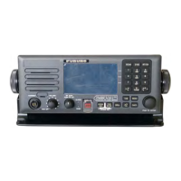
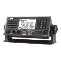
FURUNO
FS-1575/2575/5075
SP - 3 E5678S01L-M
6 TERMINAL UNIT (OPTION)
6.1 Display
IB-583 10.4” color TFT LCD, 640 x 480 dots (VGA)
IB-585 10.4” color TFT LCD, 800 x 600 dots (SVGA)
6.2 Brilliance 8 steps (IB-583), 11 steps (IB-585)
6.3 External memory
IB-583 3.5” floppy disk
IB-585 SD card: 2 GB max. or SDHC card: 32 GB max.
(SDHC card: formatted and recognized as a 2GB card)
6.4 Keyboard interface
IB-583 PS/2
IB-585 USB2.0, 1.5Mbps
6.5 Visible distance 0.7 m nominal
7 INTERFACE
7.1 Input data sentences IEC 61162-1 Ed.4 (2010-11)
Ship’s Position (L/L) GGA, GLL, GNS, RMC
Time ZDA
7.2 LAN Ethernet 10Base-T/100Base-TX
8 POWER SUPPLY
8.1 Transceiver/control unit
FS-1575 24 VDC: 5A (RX), 20 A max. (TX)
FS-2575 24 VDC: 5A (RX), 40 A max. (TX)
FS-5075 24 VDC: 5A (RX), 60 A max. (TX)
8.2 Terminal unit 24 VDC: 0.6 A (IB-583), 12-24 VDC: 0.5-0.3 A (IB-585)
8.3 Printer (PP-510, option) 24 VDC: 1.5 A
8.4 AC/DC power supply unit
PR-300 (for FS-1575, option) 100/110/200/220VAC, 1 phase, 50/60 Hz
PR-850A (for FS-2575/5075, option) 100/110/120/200/220/240VAC, 1 phase, 50/60 Hz
9 ENVIRONMENTAL CONDITION
9.1 Ambient temperature
Antenna coupler -25°C to +55°C
Indoor units -15°C to +55°C
9.2 Relative humidity 93% or less at 40°C
9.3 Degree of protection
Antenna coupler IP56
Transceiver unit IP22 (bulkhead mount only)
Terminal unit IP20 (IP22: option required for IB-585)
Control unit IP20 (IP22: option required)
9.4 Vibration IEC60945 Ed.4
10 COATING COLOR
10.1 Antenna coupler N9.5 (white)
10.2 Transceiver/control unit N2.5



 To Next Page