5. GESTURE CONTROLLER GC-001
5-2
Note 1: If NG appears for any of the self-diagnostic tests, the start up process is
stopped. Turn the power off, remove the batteries from the GC-001 and consult your
local dealer.
Note 2: Software updates are automatically started when required and start after the
start up process is complete.
Turning the power off
Press and hold to turn the power off. A message and countdown timer appear
on the GC-001 display. When the countdown is complete, the remote control turns off.
Note: Where [Auto OFF] is set to other than [OFF], if there is no operation within the
set time period, the GC-001 automatically turns off. See section 5.6.6 for details.
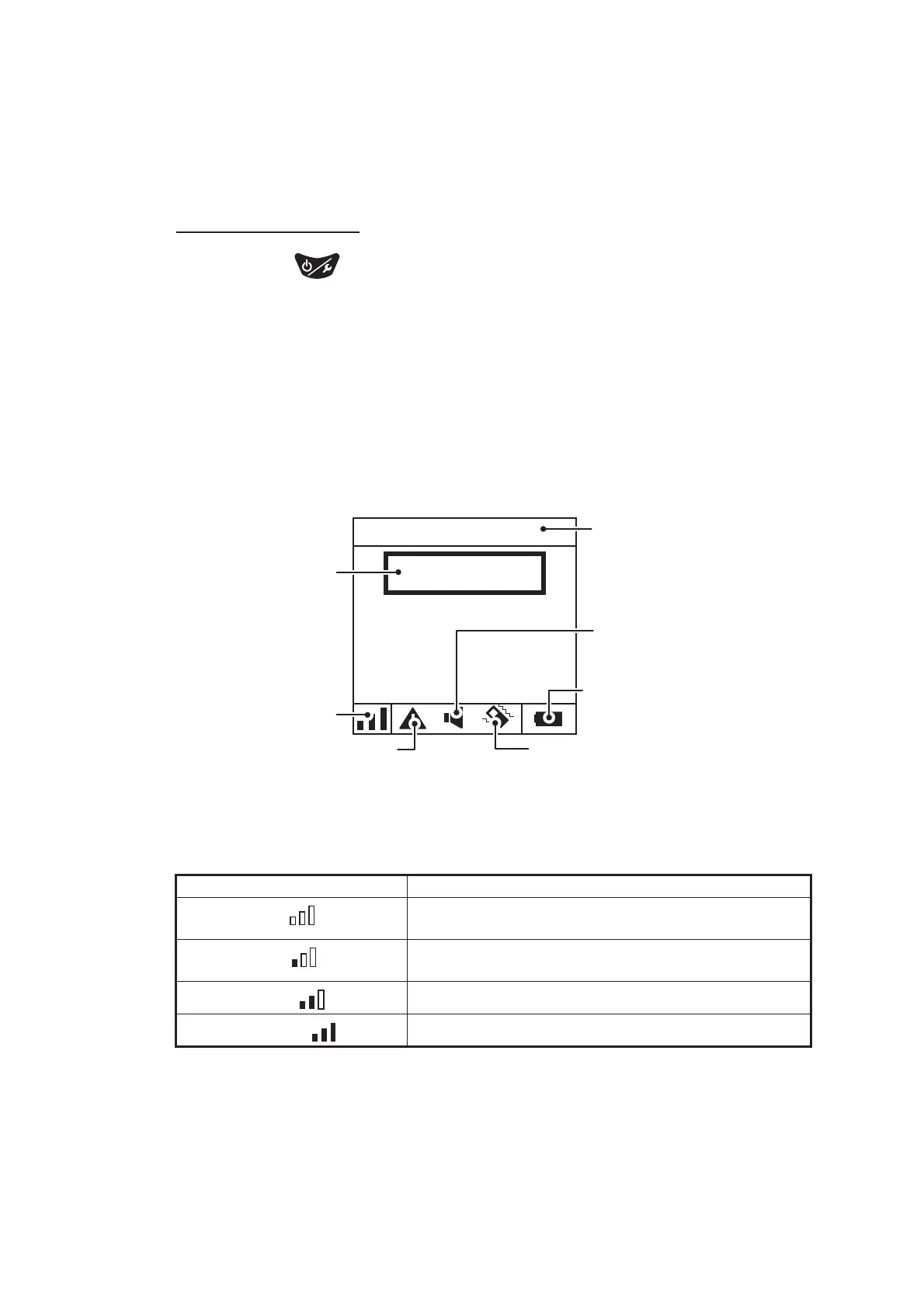
5.3 Display Overview
The figure below shows an overview of the GC-001 display in STBY mode. The GC-
001 display changes depending on the mode in use by the NAVpilot-300.
Note 1: Signal strength is indicated as one of four levels, as listed in the table below.
Distance from the processor unit, obstructions and battery voltage can reduce the sig-
nal strength. Check the signal strength when operating the GC-001.
Note 2: When the battery level is less than 10%, the GC-001 releases an alert (see
section 5.5). Low battery level can affect screen visibility and remote control functions.
To replace the batteries, see the User Guide included with the GC-001.
Signal strength indication Strength level
No solid bars ( )
Signal is extremely weak or unavailable. Move closer
to the processor unit.
One solid bar ( )
Signal is available, but weak. Some features and func-
tions may not work as intended.
Two solid bars ( )
Signal is average strength.
Three solid bars ( )
Signal is strong.
NP300-RC
HDG T
STBY
25
Paired
device
name
Signal strength
indication
Alert icon
Buzzer
setting
indication
Battery
level
indication
Vibration
setting
indication
Mode currently
in use by the
NAVpilot-300.
 Loading...