3. EQUIPMENT SETUP
3-14
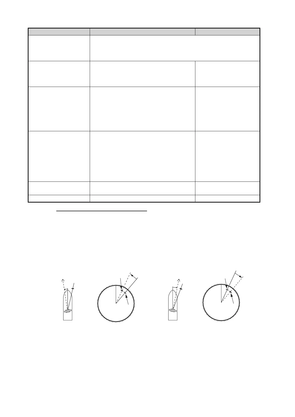
How to align the antenna heading
You have mounted the antenna unit facing straight ahead in the direction of the bow.
Therefore, a small but conspicuous target dead ahead visually should appear on the
heading line (zero degrees).
In practice, you will probably observe some small bearing error on the display because
of the difficulty in achieving accurate initial positioning of the antenna unit. The follow-
ing adjustment will compensate for the error.
1. Set your radar with 0.125 and 0.25 nm range and the head up mode.
You can select a range by using the pinch action. The range appears at the bottom
right of the screen. Range may also be selected using the slide bar displayed on
[ARPA Advanced Set-
tings]
For service technician only. Do not change these settings.
This item is available when [TX/STBY] is [ON].
Not available (grayed out) with the radar sensor DRS4DL, DRS4DL+, or
FAR-2xx8, FAR-2xx7, FAR-15x8 series radar antenna.
[TX Channel] Select [1], [2] or [3], the channel where the
interference is smallest. See the operator’s
manual for details. Available with the radar
sensor DRS2D-NXT, DRS4D-NXT.
[Auto], [1], [2], [3]
[Target Analyzer Mode] You can emphasize rain clutter or target
echoes when the target analyzer is active.
Select [Rain] or [Target] as appropriate. See
the operator’s manual for details. Available
with the radar sensor DRS2D-NXT, DRS4D-
NXT, DRS6A-NXT, DRS12A-NXT,
DRS25A-NXT.
[Rain], [Target]
[Auto acquire by Dop-
pler]
When selecting [ON], approaching targets
(ships, rain clutter, etc.) within 3 NM from
own ship are automatically acquired by the
Doppler calculated from the radar echo. See
the operator’s manual for details. Available
with the radar sensor DRS2D-NXT, DRS4D-
NXT, DRS6A-NXT, DRS12A-NXT,
DRS25A-NXT.
[ON], [OFF]
[Set Hardware to Factory
Default]
Resets the radar selected at
[Radar Source] to factory default.
[OK], [Cancel]
[Reset Default Settings] Resets [Radar] menu settings to default. [OK], [Cancel]
Menu item Description Options (setting range)
000
010
020
030
040
050
060
070
080
090
100
110
120
130
140
150
160
170
180
190
200
210
220
230
240
250
260
270
280
290
300
310
320
330
340
350
a
Target
Correct bearing
(relative to heading)
Antenna mounted error
to port
(HDG SW advanced)
Picture appears
deviated clockwise.
000
010
020
030
040
050
060
070
080
090
100
110
120
130
140
150
160
170
180
190
200
210
220
230
240
250
260
270
280
290
300
310
320
330
340
350
b
Target
Apparent position
of target
Correct bearing
(relative to
heading)
Correct bearing
(relative to
heading)
Apparent
position of
target
Apparent
position of
target
Antenna mounted error
to starboard
(HDG SW delayed)
Picture appears
deviated counterclockwise.
Front of antenna
Front of antenna
a
b