9
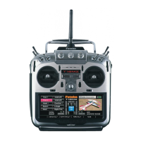
NOTE: If you need to remove or replace the transmitter battery, do not pull on its
wires to remove it. Instead, gently pull on the connector’s plastic housing where it
plugs in to the transmitter.
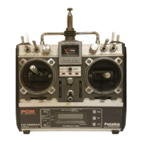
The factory default functions activated by the switches and knobs for a Mode 2
transmitter are shown below. Note that some of the functions will not operate until
activated in the mixing menus. In general, functions for a Mode 1 transmitter
reverse the E and G switches.
Switch / Knob ACRO GLID HELI
Switch A Elevator Dual Rate Elevator Dual Rate
↓
= Butterfly on
Elevator Dual Rate
↓
= PMIX-1, 2 on
Switch B Rudder Dual Rate Rudder Dual Rate Rudder Dual Rate
Switch C
↑
= ELE→FLP on
center/↓
= Idle-down
↓
= Airbrake on
↑
= ELE→FLP on
center/↓
= Idle-down
↓
= PMIX-5 on
CH 7
Switch D Aileron Dual Rate Aileron Dual Rate Aileron Dual Rate
Switch E Landing Gear GLID1FLP: Gear fwd = Throttle Hold
Switch F Snap Roll/Trainer Trainer Trainer
Switch G
↓
= PMIX-5 on back = Speed
forward = Start (Launch)
Idle-up
Switch H
↓
= PMIX-1, -2, -3 on
↓
= PMIX-1, -2, -3 on Inverted/CH5
CH6 knob Flap
(Flap trim if FLPRON on)
GLID1FLP: Flap
(Flap trim if FLPRON on)
GLID2FLP: Camber
(Flap trim if FLP-AI off)
Hovering Pitch
CH7 knob Spoiler
(disabled if AI-DIF on)
Spoiler
(disabled if AI-DIF on)
Hovering Throttle
CH8 knob CH8 CH8 CH8
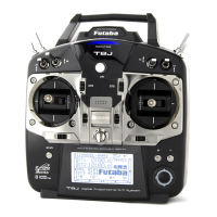
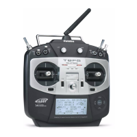
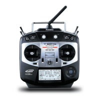
Ni-Cd battery pack
PUSH
Charging jack
Battery cover
Battery connector location
Trainer function
/DSC function connector
RF module
To remove, press the tabs together
and gently pull rearwards.
To install, line up the connector pins with
the socket in the rear of the module and
gently snap into position.