•RUDDER AUTO DUAL RATE
•This
function
automatically
switches
rudder
D/R to ON
as
the
throttle
lever
is
moved
from
LOW
to
HIGH
position. This allows a smaller rudder throw for precise inputs during rolling maneuvers (at HIGH throt-
tle) and increased throw (at LOW throttle) during stall turns, taxing, etc.
Safety Switch [31]
1
is set to ACT.
Adjust desired Rudder travel in D/R
ON using Trimmer
[21].
Throttle
Position
Trimmer 8
can
be
used
to
set
the
throttle
stick
position
at
which
D/R
is
turned
ON and OFF. Medium slow is recommended.
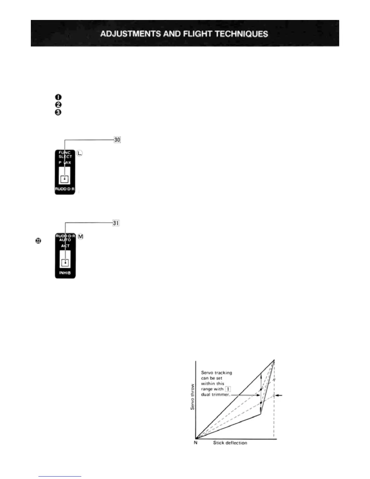
SWITCH 16 FUNCTION SELECTOR
Fig.
40
•Transmitter control switch 16
can be used as a Rudder D/R switch
or for turning the programmable
mixing function ON and OFF.
Usage is determined by the Func-
tion Select switch [30] on the trans-
mitter back panel.
• When switch 30 is set to the P
MIX position the programmed
mixing function can be turned ON
or OFF with switch 16 . The Rud-
der D/R function will not operate
unless
Rudder
Auto
D/R
function
is used.
• When switch
[30]
is set to the
RUDD D/R position, the rudder
D/R can be turned ON or OFF with
Switch 16 . In this mode, the pro-
grammed mixing function will re-
main on regardless of Switch 16 .
RUDDER AUTO DUAL RATE SAFETY SWITCH
Fig.
41
•When the Rudder Auto D/R
Safety Switch 31 is set to ACT,
rudder auto D/R is ON. If Function
Select Switch [30] is also set to
RUDD D/R, the rudder D/R can
be
turned ON and OFF with con-
trol switch 16 but the rudder auto
D/R function will still remain acti-
vated regardless of Switch 16.
•When switch
[31]
is set to INHIB,
the rudder auto D/R function is
inoperative. If Function Select
switch [30] is in the RUDD D/R
position, the rudder D/R function
can be turned ON or OFF with con-
trol switch 16 . Trimmer 21 sets
the rudder D/R and Auto D/R
deflection angles.
•USING
VTR
(VARIABLE
TRACE RATIO)
•VTR
(Variable
Trace
Ratio)
is
a
new type
of
non-linear control response. It is similar to Ex-
ponential Control, but is easier to use. Aileron
will be used as an example.
•When the Aileron LINEAR/VTR Switch [3] is
in the LINEAR position, servo travel is linear
and directly proportional to the deflection of
the transmitter control stick as shown in Fig. 42.
In the VTR position (Ail. D/R Switch 14 must
also be in D/R OFF pos.), servo maximum throw
is unchanged. However servo tracking is the same
as when the rate switch is in the D/R I ON
position up to about 80% of the transmitter
stick deflection. Servo throw then abruptly in-
creases to the same deflection as when D/R
Switch 14 is in D/R OFF position. Fig. 42
shows the servo movement curve when VTR is
used. Another way to think of VTR is as "auto-
matic dual rate" that is switched off automati-
cally as the control stick is moved past the 80%
deflection point.
•
Note: Maximum
servo
travel
is
the
same
in
both
LINEAR and VTR modes and is determined by
ATV settings or maximum travel of the servo
itself if no ATV is set.
• If rate switches are set to D/R ON while in the
VTR mode, servo tracking will revert to LINEAR
and travel is set by the D/R trimmer.
Fig.
42
•When the dual
rate switch is
ON, operation
is the same as
when the
LINEAR-VTR
switch is set to
the LINEAR
position.