1M23N26419
T18MZ SOFTWARE UPDATE CHANGES
(Editor Version: 2.4 Encoder version: 2.0)
This software updates or alters the functions and features noted below. The instructions and information that follow are meant as a supplement to the original instruction
manual that accompanied the T18MZ transmitter. Please refer to the original instruction manual where applicable, but replace the steps indicated below with these
instructions. Please note that the software update will be finalized the first time that the T18MZ is powered up, after the software has been applied. As such, it may require a
few moments before the Start screen appears. Please check to ensure that the update has been installed.
1) Select the System Menu.
2) Touch the [Information] button.
3) Confirm that the information in the display indicates the Editor and Encoder version numbers as noted above.
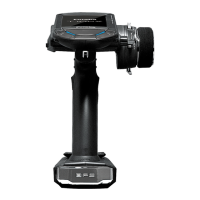
1. Variometer melody ON/OFF switch function
A function that can turn the altimeter and GPS variometer melody (function
that signifies that the aircraft is rising or diving by means of a melody) on
and off has been added.
【Setting method】
① At the linkage menu Telemetry screen, select Altimeter (Altitude) or
Altimeter (Vario).
② Set Melody to ON and press NULL and select the desired switch.
③ Set the switch ON/OFF position.
■ Only toggle switch can be selected. The alternate function (function that
repeats ON → OFF → ON →・・・each time the switch is operated)
cannot be used.
2. Extra voltage alert specifications change
The receiver and voltmeter external voltage input terminal (ExtraVoltage)
was specified to stop the alarm when the external input voltage was 0V.
However, this has been changed so that the alarm is generated even when
the external input voltage is 0V only when the alarm voltage was set to 0V.
3. Telemetry data log function
Telemetry data has been adapted to the log function which is recorded at
the SD card.
【Setting method】
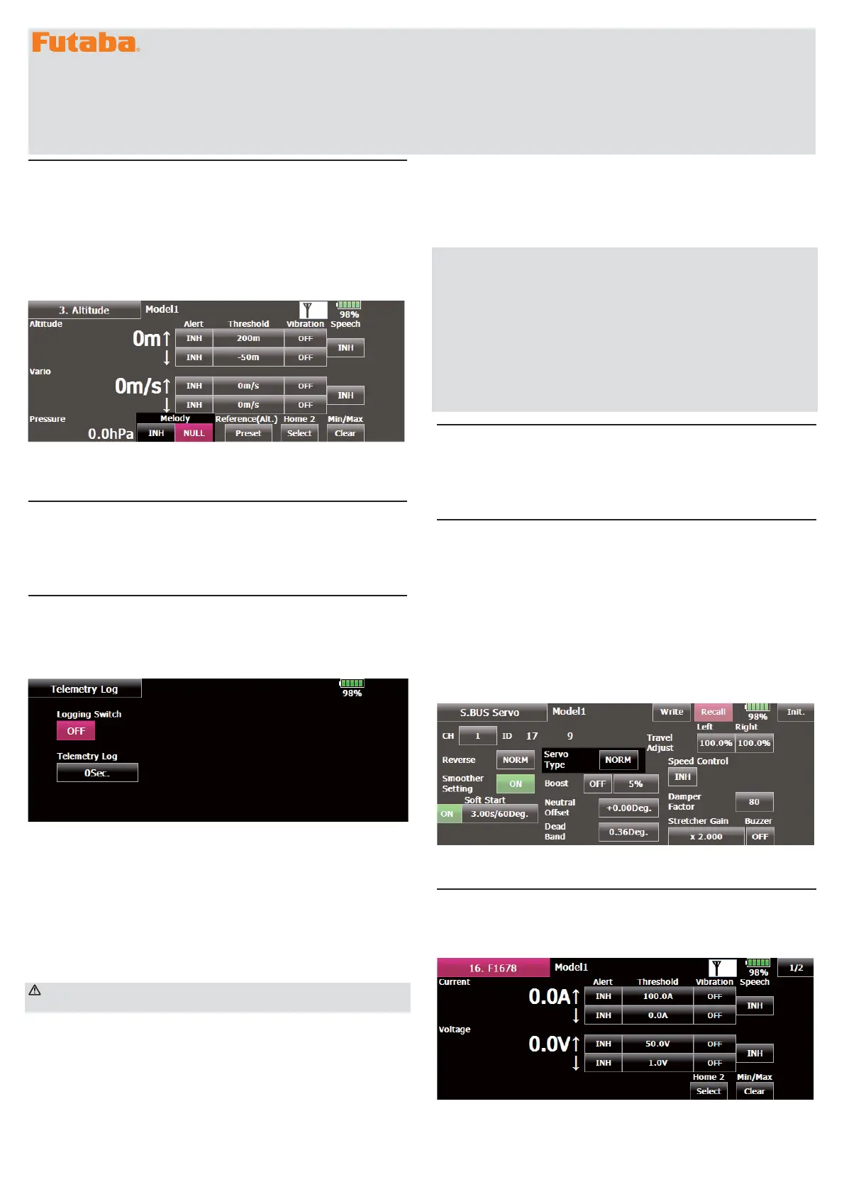
① Open the linkage menu Telemetry Log screen.
② Log recording can be started and stopped by operating a switch. The
Log Start/Stop switch is selected.
③ The log output interval can be set.
* The data to be recorded is updated at the time set by Linkage
Menu → System Type screen D/L Interval. For example, when the log
output interval is 1 second and the D/L interval is 2 seconds the same
data is overlapped and recorded twice.
【Operation method】
① Insert the SD card into the card slot.
② Set the switch set by Log Start/Stop Switch to ON. A beep sounds and a
log file is created and recording of the telemetry data begins.
AbsolutelyneverremovetheSDcardwhilelogdataisbeing
recorded.
③ Set the switch set by Log Start/Stop Switch to OFF. A beeping sound is
generated and recording of the telemetry data stops.
④ Turn off the transmitter power and remove the SD card.
■ Log file
A log file is created in the SD card LOG folder. Two files with the same
filename, but a different extension are created. (Example: 00001234.FLI,
00001234.FLD)
■ Extension FLI: Slot allocation information file
■ Extension FLD: Log data file
*When copying or moving a log file, always select both the .FLI file and
.FLD file.
Log files can be converted to CSV format by using the telemetry log
converter available at the Futaba website.
■ Notes
◇
Altimeter altitude data and GPS distance and altitude data output with
the point that time logging started as the reference (0m). When the
transmitter preset position and the log start position are different, the
transmitter display and the log data display will also be different. The
altitude and distance from the take-off position can be recorded by
starting logging immediately after take-off.
◇
The transmitter gear ratio or number of fins setting is not reflected in
the speedometer log data (speed). Multiply the gear ratio or number of
fins by the speed data.
◇
When the SD card becomes full, recording stops and does not resume
even if logging is restarted.
4. Altimeter display units change
The altimeter and GPS display units when the display units system is set to
yards and pounds has been changed.
■ Vario fpm (ft / min)
■ Pressure inHg (inch of mercury)
5.Addition of S.BUS servo setting function
A servo type setting function was added to S.BUS compatible servos other
than the S3171SB, S9071SB, S9072SB, S9074SB, and S9075SB.
■ Normal: Normal operation mode
■ Retract: Landing gear retract mode. When a load is applied to the
servo for 30 seconds without any channel operation performed from the
transmitter, the current consumption is suppressed by widening the dead
band to 40°. When channel operation is performed from the transmitter,
or the servo is moved outside the expanded dead band by an outside
force, dead band expansion is reset and returns to the original operation.
■ O.L.P. : This is the Over Load Protection mode. When a servo horn has
been locked for more than 5 seconds by a load, the servo output turns off
to protect the servo.
■ The normal mode and retract mode are applicable only to the S3171SB,
S9071SB, S9072SB, S9074SB, and S9075SB.
6.Robbe current sensor (F1678) function
The T18MZ has been made compatible with the Robbe current sensor
(F1678). The current, voltage, and battery capacity can be displayed. Refer
to the Robbe current sensor instruction manual for more information.
 Loading...