- 3 -
② Connect an S.BUS servo to the S.BUS setting connector on the back
of the transmitter. Connect the battery to the sensor unit using a 2-way
cord, etc.
*Please note, this function is not applicable to the S9070SB servo.
③ Read the servo data by touching the [Read] button.
④ An operation check signal is output to the servo from the transmitter.
When the transmitter switch or stick that controls the channel allocated to
the S.BUS servo is operated, the servo will move accordingly.
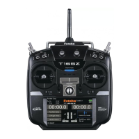
Data reset screen
This update allows the user to separately reset the information for user
menus and telemetry data, if desired. For example, it is now possible
to reset the telemetry information without impacting the other model
programming.
【Setting method】
① Open the data reset screen by touching the [Data Reset] button in the
Linkage Menu.
② To reset the user menu setting, touch the [User Menu] button. To reset
the telemetry settings, touch the [Telemetry] button.
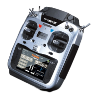
Camera function shutter switch
This update allows the user to assign a switch/position to control the
camera function of the T18MZ.
【Setting method】
① Open the camera screen by touching the [Camera] button in the System
Menu.
② To determine the switch to be used for the camera shutter, press the
switch select button located below the shutter button. Next, determine the
switch and the activation direction.
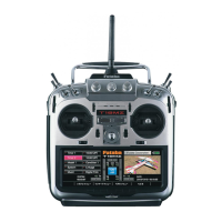
Maximum engine revolution display by each condition
It is now possible to display maximum engine revolutions by each condition.
【Setting method】
① Touch the [Condition] button on the RPM display.
② The screen that appears next denotes the maximum RPM achieved for
each of the flight conditions programmed into the transmitter.
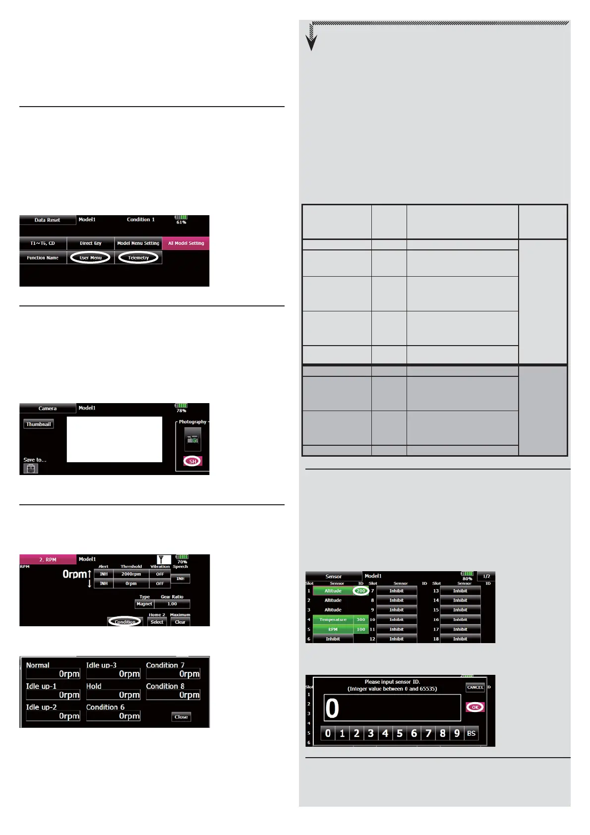
Sensor unit ID setting
There are two methodologies that may be used to register the
identification of the sensors used with the T18MZ. This may be done
manually within the transmitter's program. Alternatively, registration of the
sensor may be accomplished through the sensor unit registration function
which follows.
【Setting method】
① Open the sensor unit setting screen by touching the [Sensor] button
in the Linkage Menu. The name and ID of the sensor assigned to each
slot is displayed.
② Touch the [ID] button of the desired slot.
③ To manually enter, or change the identification of the desired sensor(s),
input the identification using the touchpad. When completed, press OK.
Sensor unit registration
The sensor unit of each transmitter slot is registered and the slot number
of each sensor unit is changed automatically.
【Setting method】
Nextexplanationisrequiredwhenusing
twoormorethesamekindofsensors.
【Example1 Altitudesensor × 1,Temperaturesensor × 1】
Asetupisunnecessary.
TwosensorsarepackedbyHUBanditconnectswithS.BUS2
ofareceiver.
【Example2 Altitudesensor × 1,Temperaturesensor × 2】
Onealtitudesensorandonetemperaturesensor,itis
unnecessarytosetup.
Sensorregistrationisneededaboutthe2ndtemperature
sensors.
<
Assignable slot
>
*Altitude sensors, GPS sensors and other
data sensor units may use multiple slots.
*The sensor which uses two or more slots
has restriction in a start slot.
Sensor
The
required
number
of slots
The number which can be
used as a start slot
Selling area
TEMP (SBS-01T) 1 slot 1 〜 31
Global
RPM
(SBS01RM,SBS-
01RO)
1 slot 1 〜 31
Voltage (SBS-01V) 2 slots
1,2,3,4,5,6,
8,9,10,11,12,13,14,
16,17,18,19,20,21,22,
24,25,26,27,28,29,30
Altitude (SBS-01A) 3 slots
1,2,3,4,5,
8,9,10,11,12,13,
16,17,18,19,20,21,
24,25,26,27,28,29
GPS (SBS-01G) 8 slots 8,16,24
TEMP125-F1713 1 slot 1 〜 31
Europe
VARIO-F1712 2 slots
1,2,3,4,5,6,
8,9,10,11,12,13,14,
16,17,18,19,20,21,22,
24,25,26,27,28,29,30
VARIO-F1672 2 slots
1,2,3,4,5,6,
8,9,10,11,12,13,14,
16,17,18,19,20,21,22,
24,25,26,27,28,29,30
GPS-F1675 8 slots 8,16,24
 Loading...