The FUTURA EG Series Machine Control System is designed to provide maximum control over grading systems at an accessible price. It is versatile and can be installed on various machines, including box blades, box scrapers, graders, mini-graders, and skid steers. The system controls most valve packages and offers both LED and a real-time LCD display to keep the user informed about blade position.
Function Description:
The EG Series Receiver detects any rotating red beam laser within its 173mm (7”) capture range, indicating the blade's position with an accuracy of 2mm (5/64”). LED indicator lights on the receiver provide the same output as those on the control box, allowing the operator to monitor blade position from the field or inside the machine. The control box enables users to configure the display to show real-time variances from the on-grade position. The receiver attaches to a standard 45mm (1 3/4”) pipe. The complete system operates on 10-30VDC.
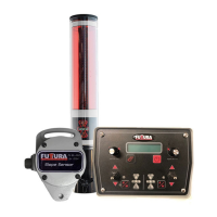
System Components:
The system includes a Control Box, Slope Sensor, Receiver, and a Cable Set. An optional Telescoping Mechanical Mast is also available.
Control Box Features:
- Left/Right On-grade Offset Knobs: These knobs adjust the on-grade position of each receiver by up to 54mm (2.13 inches), allowing the operator to move the on-grade position up or down.
- Menu Button: Used to navigate through menus for system setup. The menu flow is unidirectional. Pressing either A/M key provides a shortcut back to the main screen.
- Slope Indicator Display: Displays real-time slope from -6% to +6% in 0.5% steps.
- Left/Right Valve Raise/Lower Switches: Toggle switches for manual control of hydraulic circuits. They also function as controls within the menu to change parameters.
- Auto/Manual Indicators: Lights indicate when the system is in automatic mode.
- Left/Right Auto/Manual Buttons: Switch the system between automatic and manual control. The right button controls both sides, while the left controls only the left side, allowing for individual or combined control.
- Left/Right LED Grade Displays: These LEDs show whether the blade is above, below, or on grade. Red arrows indicate the direction the blade needs to move, with a single flashing red LED signifying the receiver is within 10mm (0.39”) of the desired grade. Green LEDs flash when the blade is within the desired "on grade."
- Power On/Off Switch: A brief press turns the system on; holding for approximately two seconds turns it off. This button also acts as a soft key for functions displayed directly above it.
Control Box Connections:
- Valve Cable Connector: Connects the valve cable to the control box.
- Remote Switch Connector: Plugs in the remote auto/raise/lower toggle switch assembly.
- Communication Connector: Receives signals from the receiver and sensors via the Node Box.
- Power Cable Connector: Provides battery power to the system.
Display Screens and Menus:
- Splash Screen: Displays System Type and Version upon power-up.
- Main Control Screens: The initial screen after a 10-second startup. Its appearance varies based on the system model and configuration.
- Single Laser Control: Shows real-time laser beam position (metric or imperial) and receiver on-grade offset.
- Single Laser with Slope Control: Displays receiver on-grade offset and desired slope.
- Dual Laser Control / Dual Laser with Slope Indicate: Shows receiver on-grade offset values for both left and right sides, adjustable via knobs. The Left Knob adjusts the left offset, and the Right Knob adjusts the right offset. Temporarily linking left and right offsets is possible by pressing the Power button once (an 'X' appears).
- Slope Indicate / Control: If the slope option is enabled, this screen displays real-time slope and direction, as well as the desired slope. The desired slope is entered via the right offset knob.
- System Lockout Screen: Appears if a lockout code is set. The factory default password is "1000." This option can be disabled by setting the password to "0000."
- Filtering: Adjusts the receiver's filtering rate to reduce jumpy behavior. The fastest setting with the fewest interruptions is recommended.
- Valve Deadband: Sets the allowable on-grade tolerance (1mm to 30mm). Valves activate only when receiver readings exceed 5mm beyond the deadband range.
- Horn: Configures the internal beeper:
- Off: Disables the beeper.
- Alert: Sets the beeper to grade alarm mode; sounds if no on-grade indication for 6 seconds in automatic mode.
- Indicate: Sets the beeper to indicate mode; sounds like a detector (double beep for too high, single beep for too low, solid beep for on grade).
- Height Adjustment: When "ON," the offset knob is enabled, allowing an adjustable 'on grade' displayed on the LCD. When "OFF" or "0," the offset knob is disabled, and 'Real Time' blade position is displayed.
- Unit Selection: Sets units to Millimeters, Inches (decimal), or Feet (10th of a foot).
- Latec Info Screen: Displays Latec information, name, and phone number.
- Installation Menu Access: Press the Menu and Power buttons simultaneously while the LATEC info screen is displayed.
Valve Settings:
- Valve1 Types (Left Side): Controls proportional time ('bang-bang'), proportional valves with integrated electronics (Danfoss), Selective Control Valve (SCV), and proportional current (variable flow) valves. Proportional current settings include 50 Hz, 100 Hz, and 200 Hz. Consult the valve manufacturer for the correct type and dither frequency.
- Proportional Time mode: Output is an on/off voltage, high current, equal to the DC input supply during valve on time.
- Proportional Current mode: Output is pulse-width-modulated, high current, equal to the DC input supply during valve on time.
- Danfoss setting: Provides low power analogue control signal and drives both high current valve outputs. One output powers the Danfoss valve, the other operates the hydraulic system loading valve.
- Valve Control Direction: Can be changed between Normal and Inverted to avoid rewiring or replumbing. Accessed by pressing Menu and Power buttons simultaneously, then pressing Menu to switch.
- Proportional Time Valve Settings (Caution: Operates Hydraulic Valve):
- Minimum Pulse Width: Sets the signal needed to move the cylinder at its slowest speed (approx. 0.5 inches per second). Pressing Menu (Test) button enters this routine. Use the right toggle switch to increase/decrease the signal. Press Menu to change direction, then adjust the cylinder speed for the opposite direction. Press Power (Stop) to store values. Different values for Up and Down may be needed to balance overall minimum speed due to gravity and cylinder volume differences.
- Valve Cycle Time: Sets how often valve pulses are sent (hits per second). Range is 1-15 hits per second (milliseconds). Lower numbers mean more hits per second. Starting at 100ms (10 hits per second) is recommended. Faster hits provide smoother response.
- Proportional Current and Danfoss Valve Settings:
- Minimum DC Pulse Width: Similar to Proportional Time, but units are in percent.
- All Valve Types:
- Valve Gain: Determines the span of error between valve onset and full operation. Higher numbers (percentage) indicate more vigorous valve action. 100% gain fully opens the valve with the slightest error. Start at 50% until Minimum Pulse width is set and hydraulics are tested. Higher numbers make the system more aggressive; lower numbers make it less aggressive.
System Options:
- Derivative Gain: Stabilizes machine control by accounting for the rate and direction of slope change (velocity feedback). Options: High, Medium, Low, Off. Medium is recommended for most installations.
- Auto Return: Sets the time for the valve to return the blade to the on-grade range after manual adjustment (0.5-second increments, 0 to 7.5 seconds). Setting to 0 disables this feature.
- Tilt Sensing On/Off: Enables/disables the optional slope sensor feature. If Off, the next menu is Factory Settings.
- Sensor Forward: Orients the sensor after mounting. Enter the number on the sensor label that faces the forward direction of travel. Real-time slope is displayed to aid mechanical adjustment to zero (level) after ensuring the control surface is level before calibration.
- Filtering (Sensor): Mathematically changes the sensor's viscosity. Slower filtering makes the sensor fluid appear thicker. Adjust based on machine and work type.
- Factory Settings: Restores all EG Series variables to default values. Defaults include: Filtering (---), On-grade dead band (10mm), Horn (Off), Height Adjustment (-On-), Units of Measurement (mm), Valve type (P.T.), Minimum PW (100ms), Valve Cycle time (250ms), Valve Gain (50%), Derivative Gain (medium), Auto Return (OFF), Language (English).
- Laser Receiver: Allows communication with other manufacturers' receivers (Apache BullsEye, Topcon LS-B series). Limited to one receiver; slope sensor cannot be implemented with these. Requires an adapter cable.
- Pass Change: Changes the system password. Factory default is "1000." Setting to "0000" disables the lockout.
- Language: Selects English or French.
- Number of Receivers: Sets the number of connected receivers (default: one, maximum: two). If two are selected and the second is not connected, an error will be displayed.
- Valve2 Select: Selects the controlling device for Valve 2 (right valve) between Right Receiver and Slope Sensor. The main control screen changes based on this selection.
- Valve 2 Settings: Follows the same procedure as Valve 1 settings.
Error Screens:
The system has built-in diagnostics. Problems with receiver or slope sensor connection, cable, or the device itself will be displayed on the main screen (e.g., "Laser Recver Bad Manual," "Slope Sensor Bad Manual").
EG Series Options (Physical):
- EG Series Remote Toggle Switch Assy: Allows switching between auto and manual modes and raising/lowering valves from the cab. The bottom toggle switches between Automatic and Manual; the top raises/lowers valves. Attaches to any lever with a universal U-bolt assembly.
- EG Series Manual Mast: Made from 2" aluminum pipe, adjustable up to 30” (760mm). Attaches to implements using an optional Shock Mount Bracket (P#: 101789) or existing laser mount. The receiver fits on top, secured by two knobs.
- Usage: Loosen the adjustment knob, move it until the receiver picks up a laser hit, then tighten it once an on-grade laser hit is achieved.
- Control Box Mount: Comes standard with a Ram Mount system for clamping to a steel rod or bolting to a flat surface, offering flexible positioning.