51837556_V_1_1.DOC
27/58
Building a serial DMX-chain:
Connect the DMX-output of the first fixture in the DMX-chain with the DMX-input of the next fixture. Always
connect one output with the input of the next fixture until all fixtures are connected.
Caution: At the last fixture, the DMX-cable has to be terminated with a terminator. Solder a 120
Ω resistor
between Signal (–) and Signal (+) into a 3-pin XLR-plug and plug it in the DMX-output of the last fixture.
Addressing
Each projector occupies 4 channels. To ensure that the control signals are properly directed to each
projector, the projector requires adressing. This is to be done for every single projector by changing the DIP
switches as set out in this table.
The starting address is defined as the first channel from which the EVO-3 will respond to the controller.
Please make sure that you don’t have any overlapping channels in order to control each EVO-3 correctly and
independently from any other fixture on the DMX data link. If two, three or more EVO-3 are addressed
similarly, they will work similarly.
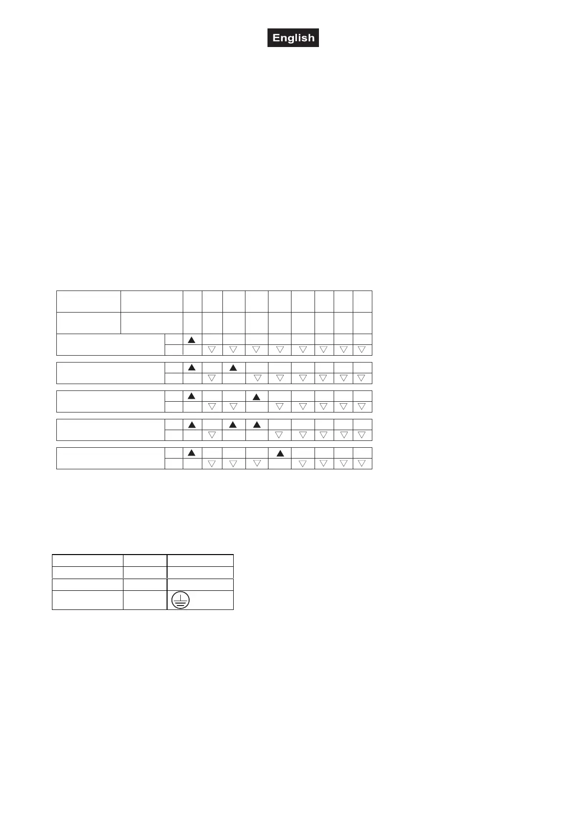
Occupation of the DIP-switches:
Device 1 - channels 1-4
On
Off
DMX-starting
address
Projector number
& channels
Off
Device 2 - channels 5-8
On
Off
Device 3 - channels 9-12
On
Off
Device 4 - channels 13-16
On
Off
Device 5 - channels 17-20
On
Off
12
4
8
16
32
64
128
256
DIP-switch no.
12
3
4
5
6
7
8
9
Setting the DMX-
starting address:
Connection with the mains
Connect the device to the mains with the enclosed power supply cable.
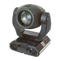
The occupation of the connection-cables is as follows:
Cable Pin International
Brown Live L
Blue Neutral N
Yellow/Green Earth
The earth has to be connected!
If the device will be directly connected with the local power supply network, a disconnection switch with a
minimum opening of 3 mm at every pole has to be included in the permanent electrical installation.
The device must only be connected with an electric installation carried out in compliance with the IEC-
standards. The electric installation must be equipped with a Residual Current Device (RCD) with a maximum
fault current of 30 mA.
Lighting effects must not be connected to dimming-packs.