Operators and Technicians Manual
© 2006 – 2007 FutureLogic, Incorporated. All Rights Reserved. MNL Page 13 of 29 12/06/2007
MNL-000030 REV.X07
Table 4-2 Base Port Cable Pin-outs
Table 4-3 Netplex Port Pin-out
Table 4-4 USB Port Cable Pin-outs
Table 4-5 Bezel LED Control Port Pin-out
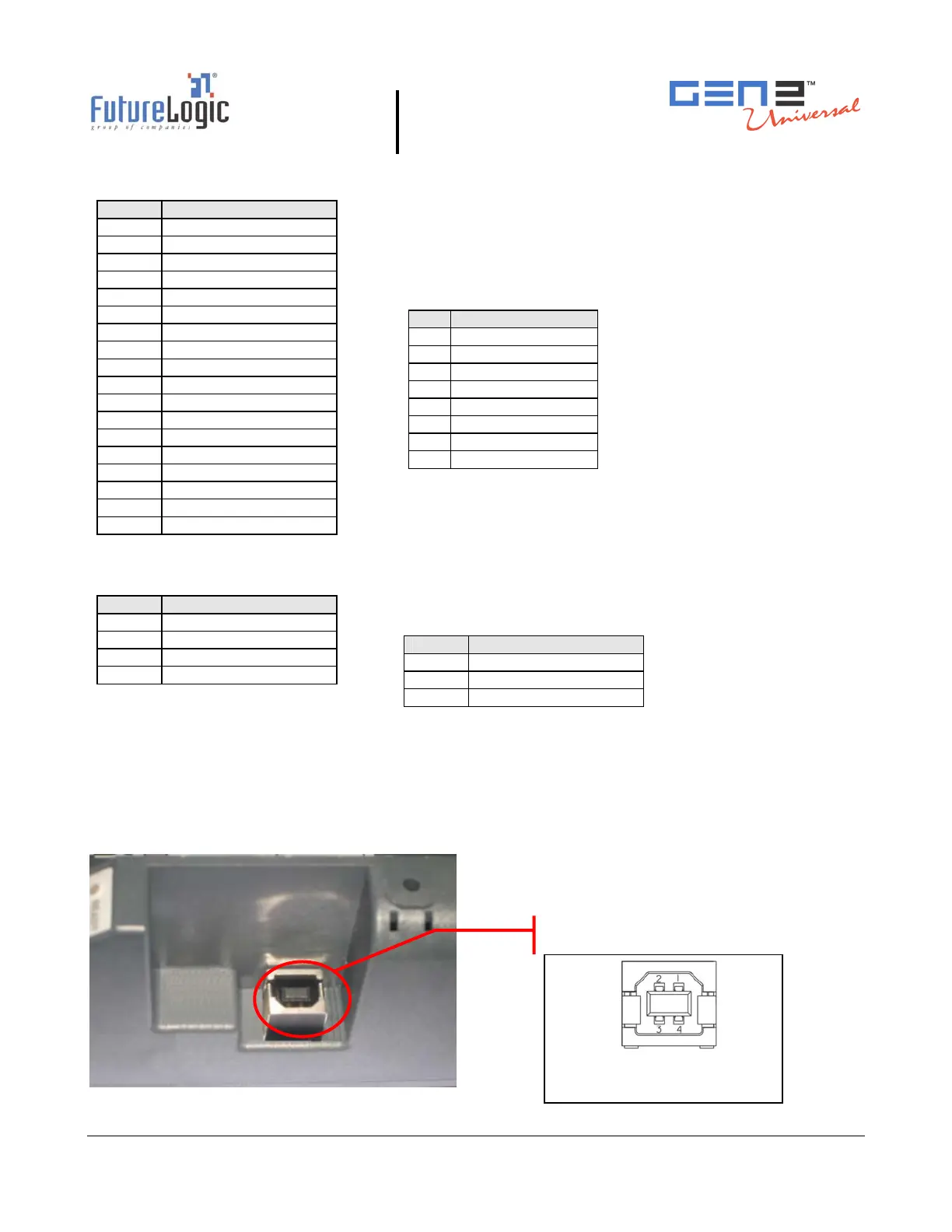
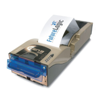
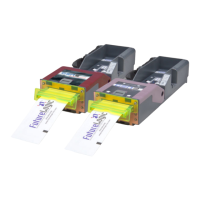
Firmware Upload Port
The Firmware Upload Port upgrades the printer firmware while the printer is still installed and
powered in the game. The printer uploads through its Firmware Upload Port just as it would
through its communications connector at the rear of the printer.
To use this port, slide the printer out until the upload port (shown in the following figure) is
visible. Then plug an appropriate upgrade cable into the printer. This connection may be made
while the power is on.
Figure 4-3 Firmware Upload Port
Pin Function
1 MRESET
2 RX1 NET
3 +13V
4 TX1 NET
5 OPTO GND
6 +24V
7 GND
8 NO CONNECT
Pin Function
1 RAW BGND
2 D-
3 +13V
4 SWITCHED 24V
5 DTR 232
6 MRESET
7 D+
8 RAW 24V
9 RTS 232
10 RX2/SCL
11 TX2/SDA
12 RX1/232
13 TX1 232
14 TX1 NET
15 RX1 NET
16 OPTO GND
17 DGND
18 +9 – 14V
Pin Function
1 USB BUS SUPPLY
2 D-
3 D+
4 GND
Pin Function
1 SWITCHED 24V
2 NO CONNECT
3 GND
Firmware Upload Port
Connector: Molex 6717101-000
Mate: USB B Plug