Operators and Technicians Manual
© 2006 – 2007 FutureLogic, Incorporated. All Rights Reserved. MNL Page ii of 29 12/06/2007
MNL-000030 REV.X08
List of Figures
Figure 2-1 Operator Indicators and Controls.......................................................................2
Figure 2-2 Load a Paper Stack ............................................................................................5
Figure 2-3 Feed Paper into Paper Loading Slot....................................................................5
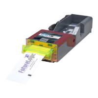
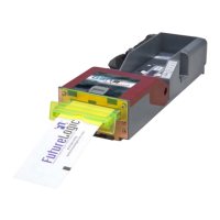
Figure 2-4 Sample Configuration Ticket..............................................................................6
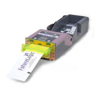
Figure 2-5 Remove the Paper ..............................................................................................6
Figure 2-6 Open the Lid......................................................................................................7
Figure 2-7 Clear the Paper Jam ..........................................................................................7
Figure 3-1 Ground Screw and Copper Grounding Clips Location ........................................8
Figure 3-2 Disconnect the Coiled Cable Connector .............................................................9
Figure 3-3 Slide the Printer until It Locks ...........................................................................9
Figure 3-4 Remove the Paper ............................................................................................10
Figure 3-5 Front Locking Bar............................................................................................10
Figure 3-6 Push Release Bar.............................................................................................10
Figure 4-1 Front Bezel LED Control Port...........................................................................11
Figure 4-2 USB/Netplex Interface Cable ...........................................................................12
Figure 4-3 Firmware Upload Port ...................................................................................... 13
Figure B-1 Ticket Dimensional Specification ..................................................................... 16
List of Tables
Table 2-1 Keypad LEDs Status Reporting Printer Condition ..............................................3
Table 2-2 Bezel Display Status ..........................................................................................3
Table 2-3 Sensors..............................................................................................................3
Table 2-4 Errors and Error Descriptions............................................................................4
Table 4-1 Front Bezel LED Control Port Pins ...................................................................11
Table 4-2 Base Port Cable Pin-outs ................................................................................. 13
Table 4-3 Netplex Port Pin-out.........................................................................................13
Table 4-4 USB Port Cable Pin-outs..................................................................................13
Table 4-5 Bezel LED Control Port Pin-out ........................................................................13