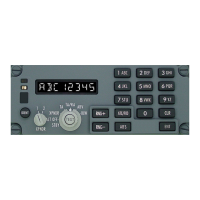
Pilot’s Guide G7490-07
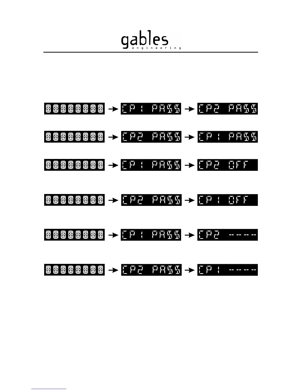
Figure 2 – Test sequence with the XPNDR Select Knob set to “1”
Figure 3 - Test sequence with the XPNDR Select Knob set to “2”
Figure 4 - Test sequence with the XPNDR Select Knob Set to “1”
and Module 2 not energized (i.e.: Circuit breaker pulled)
Figure 5 - Test sequence with the XPNDR Select Knob set to “2”
and Module 1 not energized (i.e.: Circuit breaker pulled)
Figure 6 - Test sequence with the XPNDR Select Knob set to “1”
and communication problem between Module 1 and Module 2
Figure 7 - Test sequence with the XPNDR Select Knob set to “2”
and communication problem between Module 1 and Module 2
G7490-07 Pilot’s Guide Rev 01
COPYRIGHT © Gables Engineering, July 28, 2004
Page 5 of 17