The user has the option of keeping the original ignition switch or completely removing it.
be started with either the “Start/Stop
ignition key. If eliminating the Ignition Switch, cut all wires as shown.
The vehicle can then only be started using the
) an optional relay when your vehicle uses both an
will need to be high enough to carry the
Battery, Ign1, Starter, ACC
before cutting any ignition switch wires
The RED wire is used to power
Before connecting this wire you must
wire coming from the ignition switch
or it can be connected directly to the + (pos) terminal on the
Solder connect the C1 RED wire
wire coming from the Ignition switch
. At the same time that you connect the
C1: RED wire, also solder connect the
Before connecting this wire you must first find the
wire coming from the ignition switch. The
through the Park/Neutral safety switch (au
tomatic transmission) to the starter
solenoid. Insure that you DO NOT by
pass the Park / Neutral switch; otherwise the engine could be started while in
The ACC circuit has power applied to it only when the ignition key is in the ACC position or when the “Start Stop
Engine” button is in the ACC mode. No power is applied during the engine starting cycle
Solder connect the C1: BLUE wire to the
coming from the ignition switch
wire is used to send +12v
to the ignition system and engine computer when the ignition
position. Solder connect the C1
(ignition/computer) wire coming from the Ignition switch.
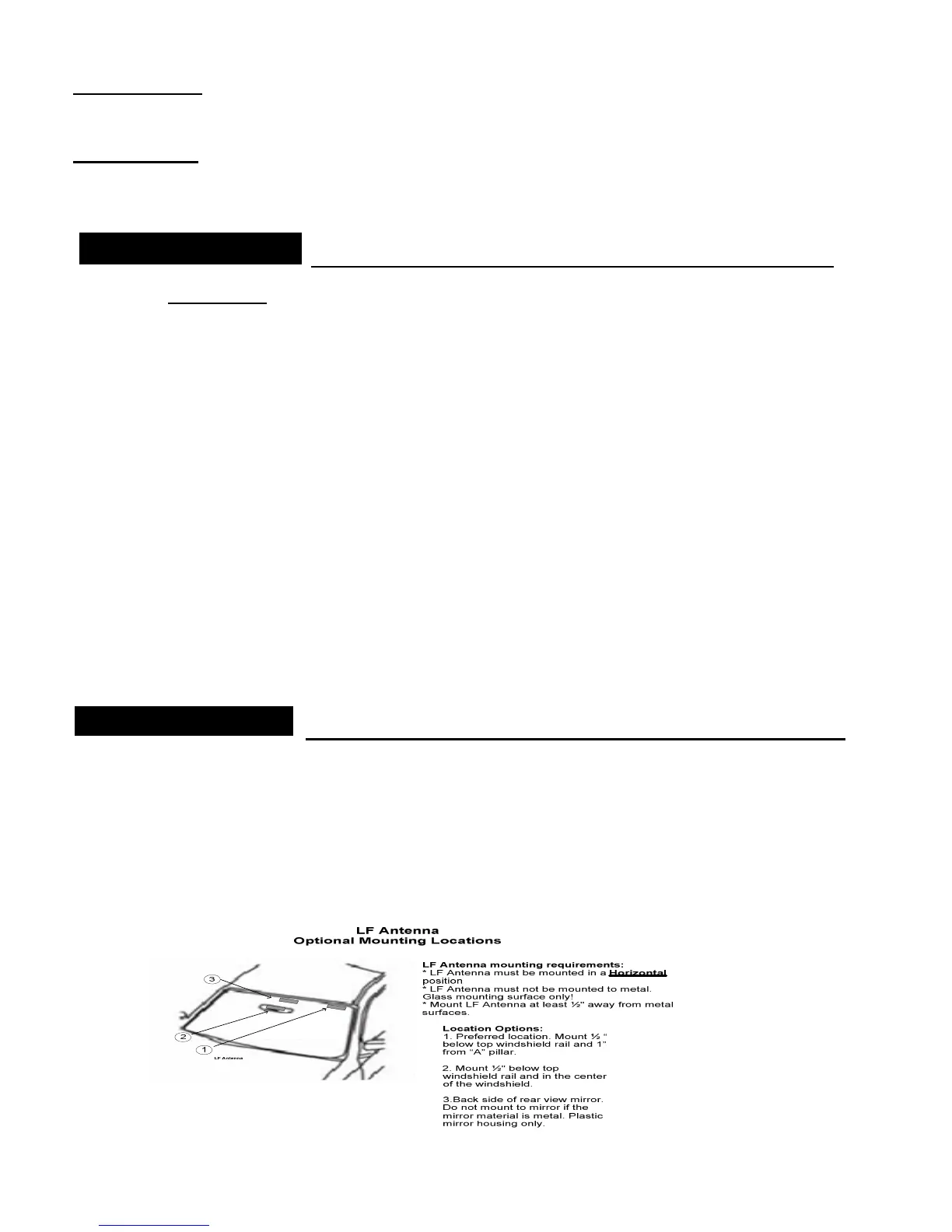
Low Frequency (LF) Antenna
The LF antenna is used for the RF
not be placed directly on any metal surface.
antenna must be mounted in a horizontal position.
2 pin LF antenna into the Control Module as
best location is usually on the
To optimize the RFID range other
locations on a glass surface can be tested. Before
may further optimize the key
 Loading...