Chapter 3 -- Instrument Circuitry--Reference 3000 Schematic/Block Diagrams
3 - 4
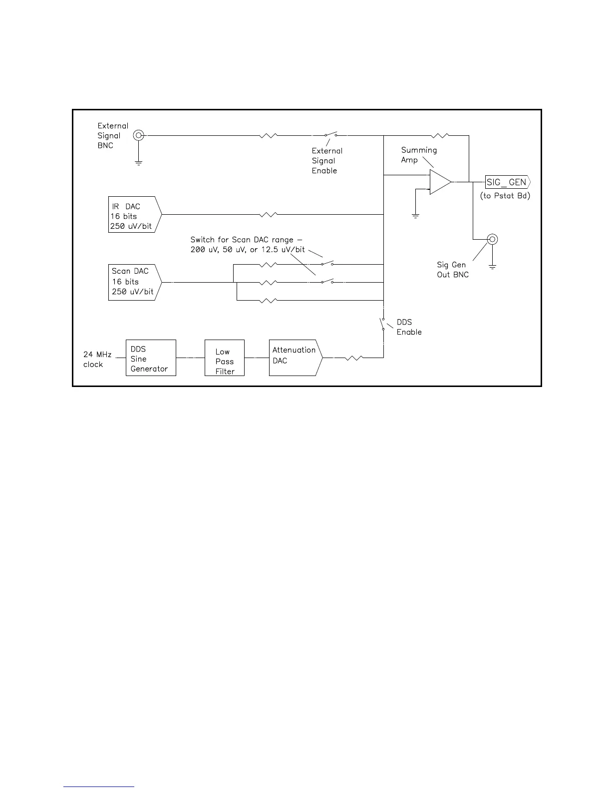
Figure 3-2
Reference 3000 Signal Generation Circuitry
Notes on Figure 3-2:
• All the resistors summing voltages into the Summing Amplifier input do not have values shown on the
diagram. Their values depend on scaling factors too complex for this simplified diagram.
• The IR DAC has a ± 8 volt full-scale range.
• Calibration components are not shown.
• The DDS can generate fixed amplitude sine waves with frequencies between 1 MHz and 1 mHz. In
practice, Gamry’s EIS300 software uses the Scan DAC to generate sine signals if frequency is below 1
Hz.
The low pass filter removes high frequency distortion in the “raw” DDS output.
The attenuator scales the DDS. The maximum output signal is 5.979 volts peak-to-peak and the
minimum is approximately 11 µV peak-to-peak.
• The BNC connector for Sig Gen out is lightly filtered using an RLC circuit.