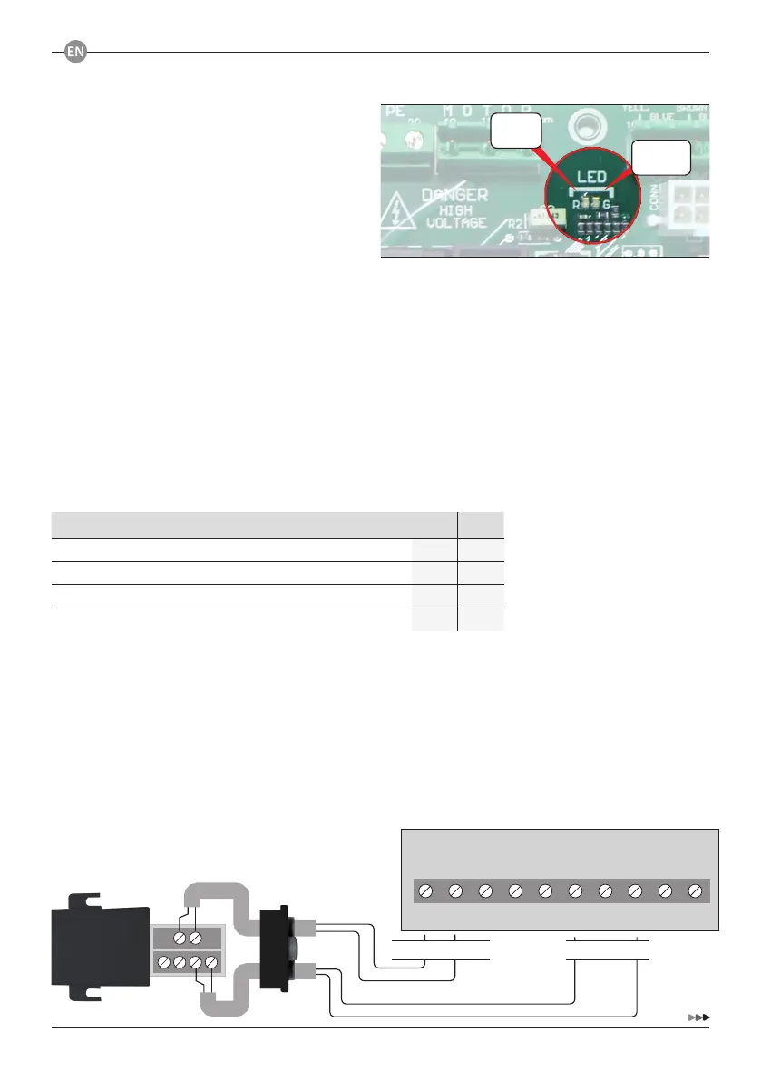
RED
LED
GREEN
LED
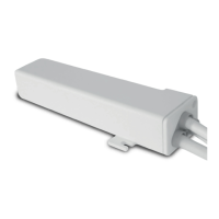
1 2 3 4 5 6 7 8 9 10
24Vac SAF STOPCOM COM GRDSS DW UP
P. Supply 24Vca signal
13
1. POWER
When you activate the board the red LED
switches on steadily for about 3 seconds.
After about 1 second, the green LED will flash a
number of times equal to the review.
When the red LED switches off, the green LED
switches on steadily indicating that the switch on
procedure of the card is completed and now it is
ready for operation.
2. OPERATING LOGIC
The control unit has 4 operating logic:
1. Automatic: opening and closing are automatic.
2. Dead-man in closing: opening is automatic while closing is dead-man.
3. Start-Stop Multi-residential: opening and closing via dedicated controls (terminals 7-8 and 8-9 or
UP/DOWN buttons on the integrated keyboar) are in automatic logic. The Start-Stop (terminals 6-8)
instead always controls the opening until the door is fully open. When the door is fully open the
Start-Stop controls closing.
4. Dead-man in opening and closing.
The logic of operation is selected using DIP 1 and 2 according to the following table:
2.1 WIRELESS OPERATING MODE
This operation mode requires:
1. Selection of the operating mode
2. Connection of a radio receiver QCRS1:
2.1.1 WIRELESS OPERATING MODE “AUTOMATIC”
- DIP1 and DIP2 in OFF
- [1 - 2] > Power supply
- [6 - 8] > Signal
OPERATING LOGIC DIP 1 DIP 2
Automatic
OFF OFF
Dead-man in closing / Automatic in opening
OFF ON
Start-Stop Multi-residential
ON OFF
Dead-man in opening and closing
ON ON