123 45
1 2 3
4 5 6
7 8
0
9
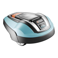
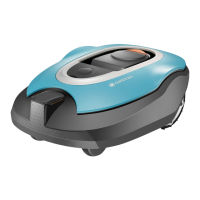
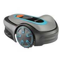
GARDENA
Start
1
2
3
4
5
6
pen the connector and lay the wire ends in the recesses on
2. Press the connectors together using a pair of pliers.
ut off any surplus boundary wire. Cut 1 to 2 cm above the
ress the connectors onto the contact pins, marked A, on
the charging station. It is important that the right-hand
wire is connected to the right-hand contact pin, and the
left-hand wire to the left-hand pin.
un the guide wire through the slot at the bottom of the
it the connector to the guide wire in the same way as for
the boundary wire, according to the instructions above.
sten the connector to the contact pin marked Guide on
ay the guide wire at least 2 metres straight out from the
front edge of the charging station.
un the guide wire to the point on the boundary loop the
connection will be made. Avoid laying the wire at tight
ut the boundary wire with a wire cutters at the centre of
the eyelet that was made in point 2.3.
onnect the guide wire to the boundary wire using the
accompanying couplers. Press the couplers completely
together with a pair of pliers.
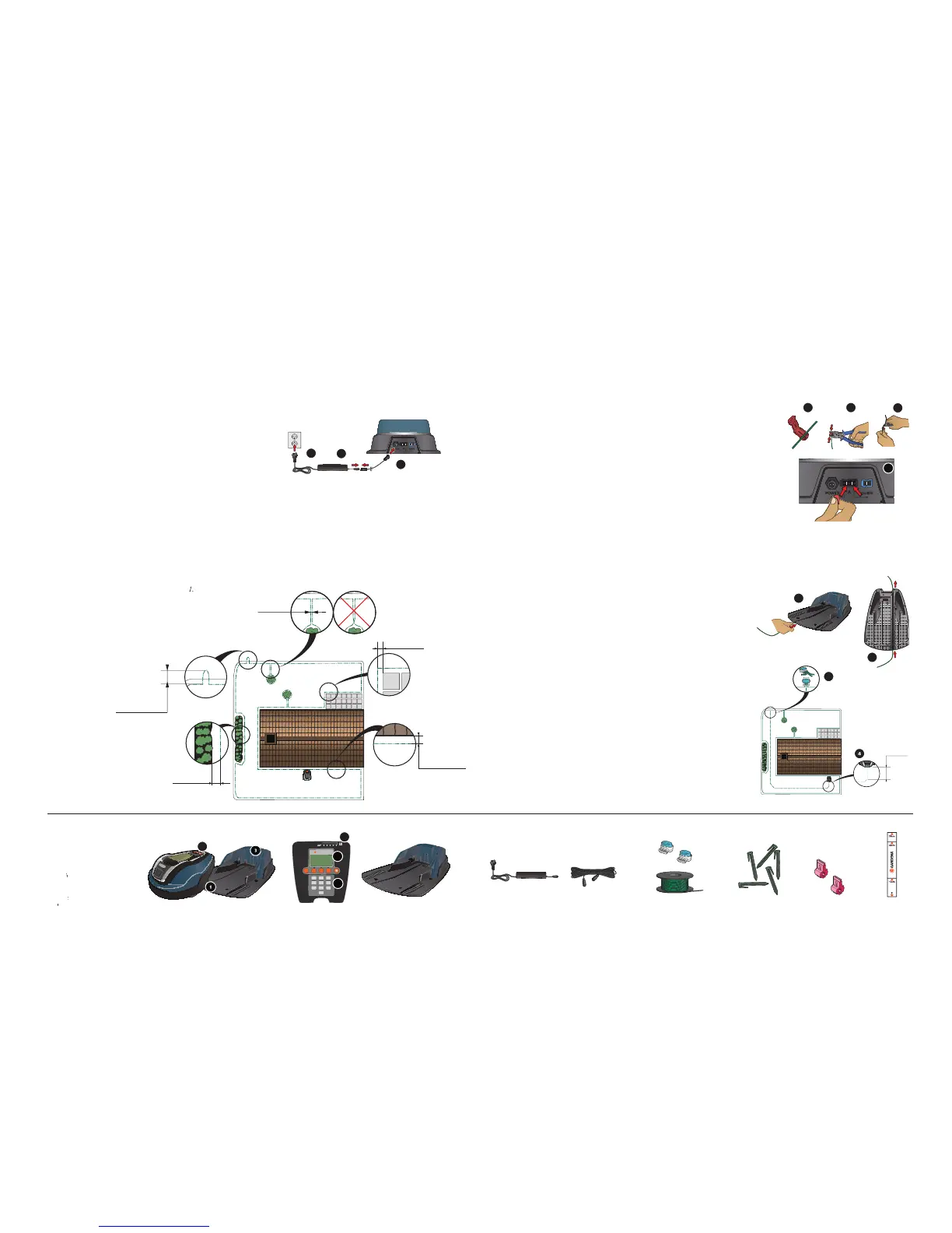
Placement of and connecting the charging station
See chapter 3.2 in the Operator’s Manual.
Charging the battery and placement
See chapters 3.3 and 3.4 in the Operator’s Manual .
lace the charging station at a central position in the work
area, with a lot of open space in front of the charging
station and on a relatively horizontal surface.
onnect the transformer’s low voltage cable to the
charging station and the transformer.
3. Connect the transformer to a 230 V wall socket.
lace the R40Li in the charging station to charge
the battery while you are laying the boundary wire.
Set the main switch to position
un the boundary wire ensuring it forms a loop
ake an eyelet at the point where the guide wire
will be connected later (see point 4.5).
Connecting the boundary wire
See chapter 3.5 in the Operator’s Manual.
Placement of and connecting
See chapter 3.6 in the Operator’s Manual.
LED for function check of the LED f
Cutting height indication