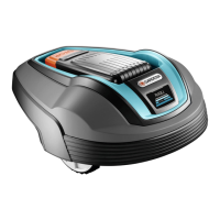
1. STOP button
2. LED for function check of the charging station,
boundary and guide wires
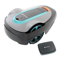
3. Charging station
4. ON/OFF button
5. Park button
6. Start button
7. Start/Schedule button
8. OK button
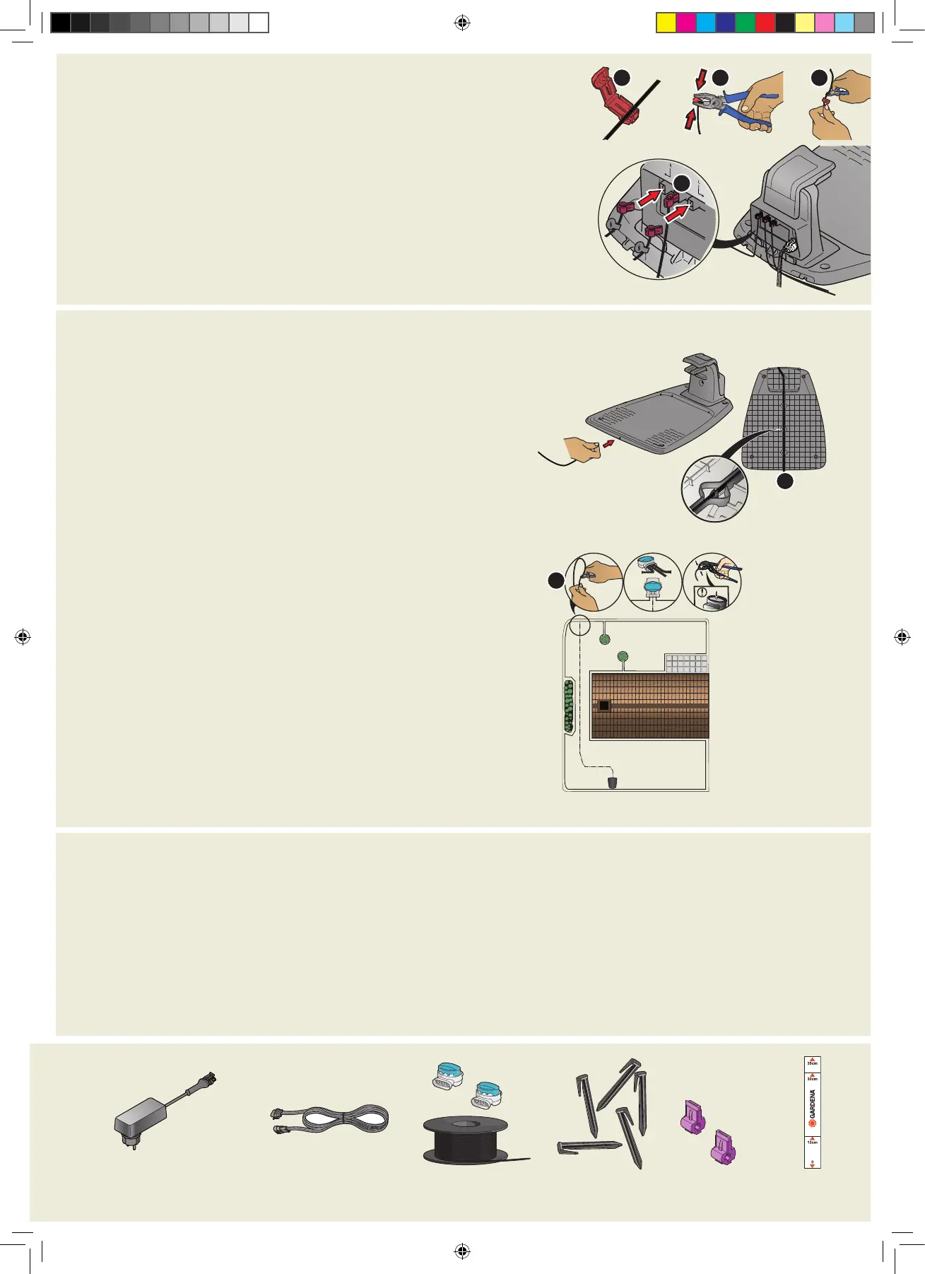
3. To connect the boundary wire
1. Open the connector and lay the boundary wire in the connector.
2. Press the connector and the wire together by using a pair of pliers.
3. Cut off the wire 1-2 cm / 0.4-0.8 in. after the connectors.
4. Press the boundary wire connectors onto the contact pins marked L (left) and R (right) on the charging station.
NOTE: The right-hand wire must be connected to the right-hand contact pin on the
charging station, and the left-hand wire to the left-hand pin.
4. To install and connect the guide wire
Install a guide wire to lead the robotic lawn mower to remote parts of the lawn and
to help it to find the charging station.
1. Push the guide wire through the bottom of the charging station and fasten it into
place using the snap locks.
2. Fit the connector to the guide wire in the same way as for the boundary wire,
according to the instructions above.
3. Press the guide wire connector onto the contact pin marked GUIDE on the
charging station.
4. Pull the guide wire a minimum of 1 m / 3.3 ft. straight out from the front edge of
the charging station.
5. Lay the guide wire from the charging station to the point on the boundary wire
(eyelet) where the connection is made using stakes supplied or bury the wire.
NOTE: Do not lay the guide wire in sharp bends and it cannot cross the boundary
wire that for instance is laid out for an island.
6. Cut the boundary wire at the center of the eyelet that was made in step 2.3.
7. Connect the guide wire to the boundary wire by inserting the boundary wires
and guide wire in the coupler, and pressing the coupler together with a pair of
pliers.
NOTE: After the guide wire is installed, attach the charging station to the ground
with the supplied screws and allen key.
NOTE: For optimal performance through narrow passages please ensure the
guide wire is laid correctly through it. Please read the Operator‘s manual for
further instructions.
Power supply
(the appearance of the power supply
may differ depending on market)
Low voltage cable Boundary wire and
couplers
Stakes
Connectors
Measurement
gauge
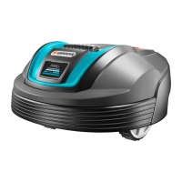
To stop the product
1. Push the STOP button.
5. To start and stop the robotic lawn mower
To start the product
1. Push the ON/OFF button for 3 seconds.
2. Enter the PIN code.
3. Select the operating mode.
To enter the factory PIN code
1. Push the ON/OFF button.
2. Push the Start/Schedule button.
3. Push the Start button.
4. Push the Park button.
NOTE: You can change the PIN code in the
GARDENA Bluetooth® App.
1
2
4
3
7
1
QG_Minimo_Gardena.indd 3QG_Minimo_Gardena.indd 3 2021-03-02 11:19:102021-03-02 11:19:10
 Loading...