13-8-619 Page 18
WARNING
Operation of the unit with improper relief valve setting can result in severe
personal injury or machine damage. Ensure properly set valves are installed
and maintained.
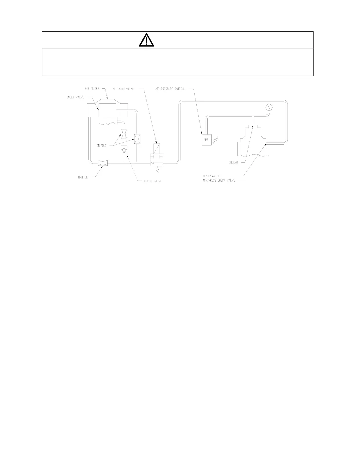
Figure 4-1 – CONTROL SCHEMATIC
AIR CONTROL COMPONENTS - All units incorporate the following air control components. See
Figure 4-1 for schematic tubing diagram.
Inlet Valve - The inlet valve is a normally opened, pneumatically closed valve. The inlet valve is
controlled by a solenoid valve, which in turn is controlled by the AutoSentry T controller, The inlet valve
closes to unload the compressor and opens to load the compressor. At shutdown the inlet valve closes to
function as a check valve and to prevent the backflow of air and oil. The seals will need to be replaced
periodically. The interval will depend on the environment and the operating conditions.
Solenoid Valve (
Figure 4-1) - The solenoid valve is operated by the controller. When energized, the valve closes, the inlet
valve opens and the package starts compressing air. When the solenoid valve is de-energized, it closes
the inlet valve and relieves the pressure in the reservoir.
Minimum Pressure/Check Valve (Figure 5-4, page 30) - An internal spring-loaded minimum pressure
valve is installed prior to the aftercooler to maintain a positive pressure on the oil system even when the
air service valve is fully open. This valve senses upstream pressure. If demand for air exceeds the
compressor capacity, the valve throttles the flow to maintain a minimum pressure on the upstream (oil
reservoir) side of the valve. When pressure rises above the minimum pressure (standard setting 40 to 45
PSIG) the valve reaches the full open position.
A check valve incorporated in the minimum pressure valve prevents backflow of air from the shop air line
when the unit stops, unloads or is shut down.
302EBA797-C
Ref. Drawin