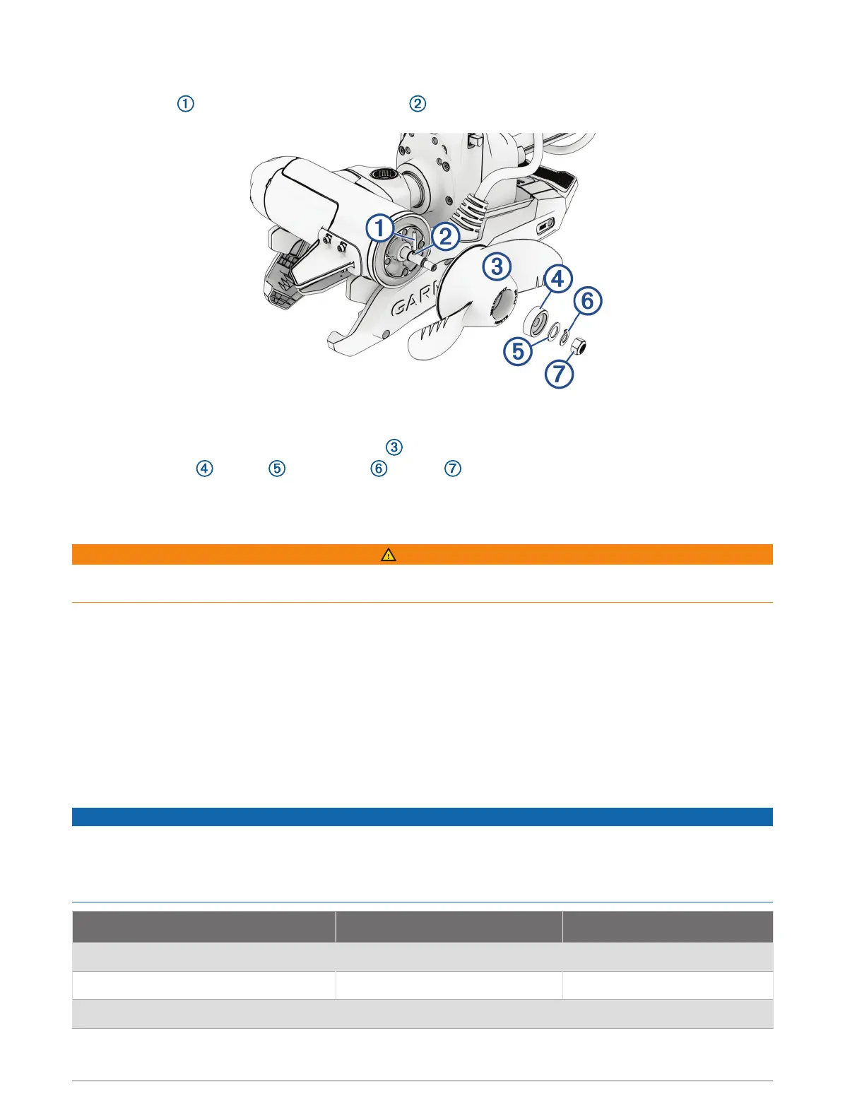
Installing the Propeller
1 Insert the pin through the propeller motor shaft .
2 If necessary, rotate the motor shaft to orient the pin horizontally so it is less likely to fall out during
installation.
3 Align the channel on the inside of the propeller with the pin, and slide the propeller onto the motor shaft.
4 Place the anode , washer , lock washer , and nut onto the end of the motor shaft.
5 Using a
9
/
16
in. (14mm) socket, tighten the lock nut to 6lbf-ft (8.13N-m) to secure the propeller.
Connecting to Power
WARNING
To avoid possible personal injury or property damage, the circuit breaker must be in the off position before you
connect the power cables from the trolling motor.
1 Route the power cable to the breaker panel or the location where you plan to install the breaker.
2 If necessary, extend the power cable using the appropriate wire gauge based on the length of the extension
(Power Cable Extension, page7) using solder and heat-shrink tubing.
3 Install a trolling motor plug and receptacle rated for 60A or greater where the power cable enters a bulkhead
(optional).
4 Connect the power cable to a circuit breaker rated for 60A (continuous).
5 If necessary, connect the circuit breaker to a 60A, 24 or 36Vdc power source.
Power Cable Extension
You can extend the power cable using the appropriate gauge of wire based on the length of the extension.
NOTICE
Power cable extensions must use single-conductor wire, with a minimum 75°C (167°F) insulation, that is not
bundled, not sheathed, and not run through conduit. If you are using wire with 105°C (221°F) insulation or better,
you can bundle up to three conductors inside a sheath or conduit outside of engine spaces.
When installing the power cable extension, you must follow industry standards and best practices.
Extension length Minimum wire gauge Optimal wire gauge
0 to 3m (0 to 10ft. ) 6AWG (16mm
2
) 6AWG (16mm
2
)
3 to 4.6m (10 to 20ft.) 6AWG (16mm
2
) 4AWG (25mm
2
)
4.6 to 9.1m (20 to 30ft.) 6AWG (16mm
2
) 2AWG (35mm
2
)
7