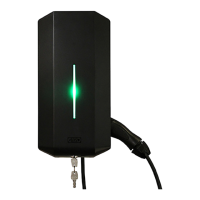
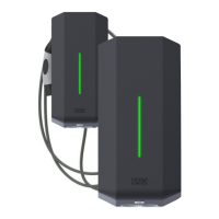
INSTALLATION OF STANDALONE TWIN
TWIN 3,7 kW = MAX 16 A
TWIN 7,4 kW = MAX 32 A
TWIN 11 kW = MAX 16 A
TWIN 22 kW = MAX 32 A
INSTALLATION OF STANDALONE TWIN
• Use conductors that are dimensioned in accordance with
local electrical regulations. The selected cable must be able
to sustain periods of constant load of up to 63A.
• The installation must be carried out by an authorized installer.
• Left hand side PCB (CC1) controls the left side outlet and right
hand side PCB (CC2) controls the right hand side outlet.
• TWIN 1-phase models use L1 for left hand side outlet and L2
for right hand side outlet.
1. Select suitable group fuse and cable dimension for the
electrical installation. Make sure to consider the cable length
during calculation to avoid risk of voltage drop.
(figure 3) shows the needed ampere (A) for each TWIN model.
Note: Due to high currents for a long time in the cable, there is a
high risk of voltage drop if the cable is under-dimensioned which
can damage the electronics in an EV.
2. Fill in the fuse and cable information in the Warranty form
located in the installation manual that is included in the box.
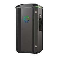
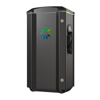
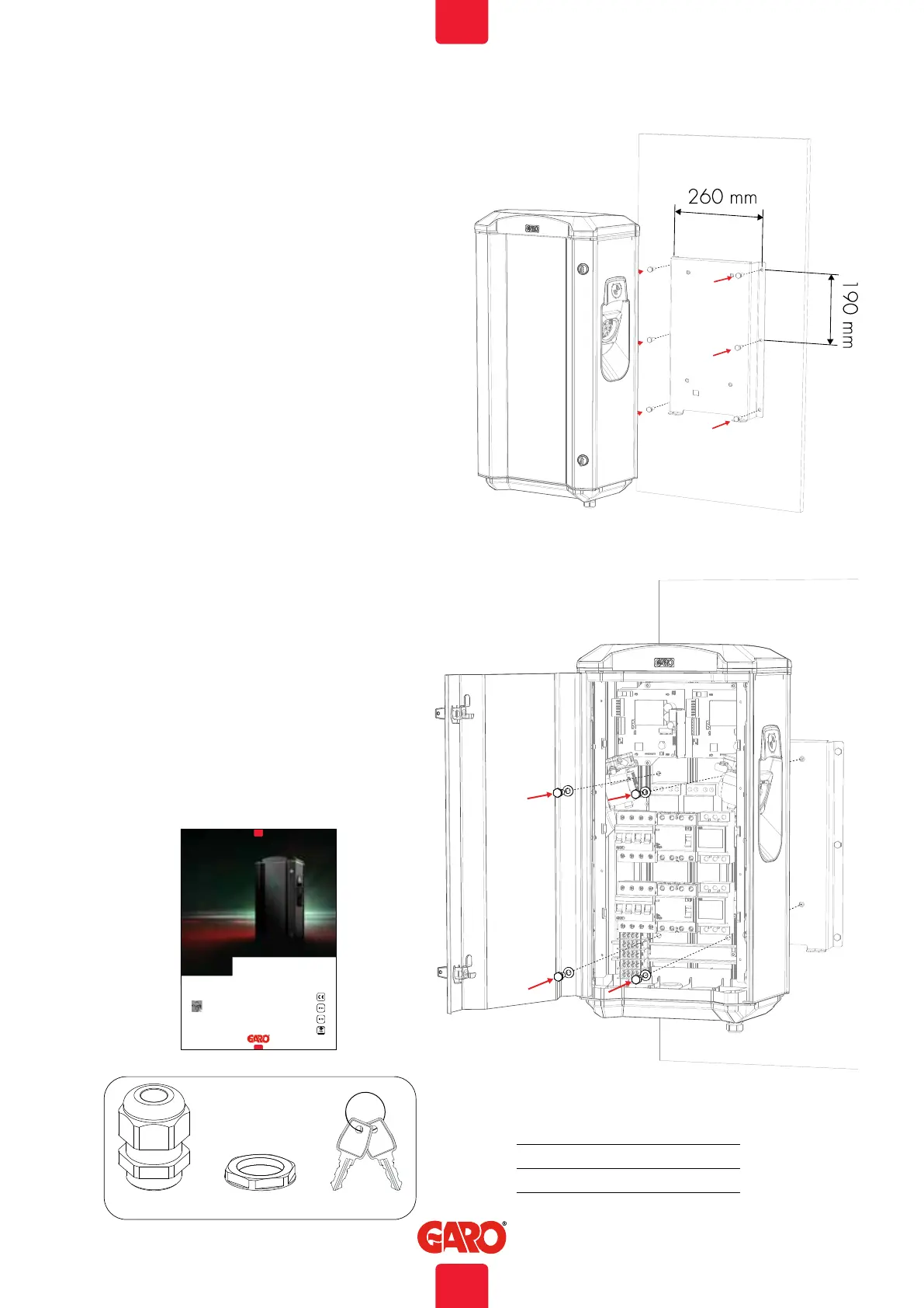
3. Mount the TWIN on a wall or pole according to picture 1-7.
Note: Wall installation of TWIN requires a minimum 20mm
distance between the wall and the TWIN to ensure correct
cooling, see (figure 4).
When TWIN is installed on a pole, the holes at the back side of
the TWIN should be covered/closed by attached screws, see
(figure 7).
(figure 1)
6 Ø 8,5mm (screws not included)
4x M8 L20mm
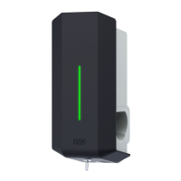
GARO TWIN+
Box 203, SE–335 25 Gnosjö
Phone: +46 (0) 370 33 28 00
info@garo.se
garo.se
Manual 380237
Installation / Instruktionsmanual
GARO AB
SE
Manual
3X M16 3X M16 2X
(figure 2)
(figure 3)
MAX Ampere per modell
5
EN
 Loading...