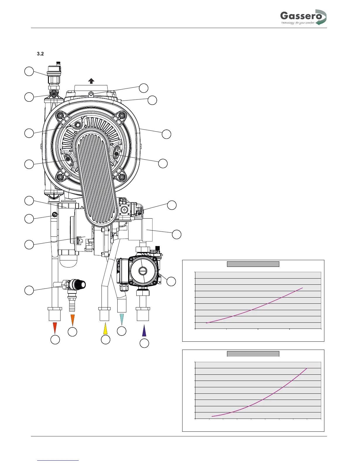
KEY
1 - Pump
2 - Venturi Adapter
3 - Gas Valve
4 - Ignition Electrode
5 - Heat Exchanger
6 - Thermal fuse
7 - Flue Gas Temperature Sensor
8 - Automatic Air Vent
9 - Manuel Air Vent
10 - Flue gas tempertaure sensor
11 - Ionization electrode
12 - Syphon
13 - NTC sensor
14 - Fan
15 - Safety Relief Valve
Technical features
8
Water pressure losses on Wallcon 67
0
10
20
30
40
50
60
70
80
90
0 500 1000 1500 2000 2500 3000 3500 4000 4500
Water flow rate(L/h)
Water pressure losses (KPa)
Water pressure losses on Wallcon 42/50
6
11
16
21
26
31
36
41
46
51
800 1200 1600 2000 2400
Water flow rate(L/h)
Water pressure losses (KPa)
1
2
3
4
5
6
7
8
9
10
11
12
13
14
15
R
G
Sc
M
Sr
WALLCON 42/50/67 HYDRAULIC DIAGRAM