04. Set up your WARFET Power Module with Tactical Programming Card
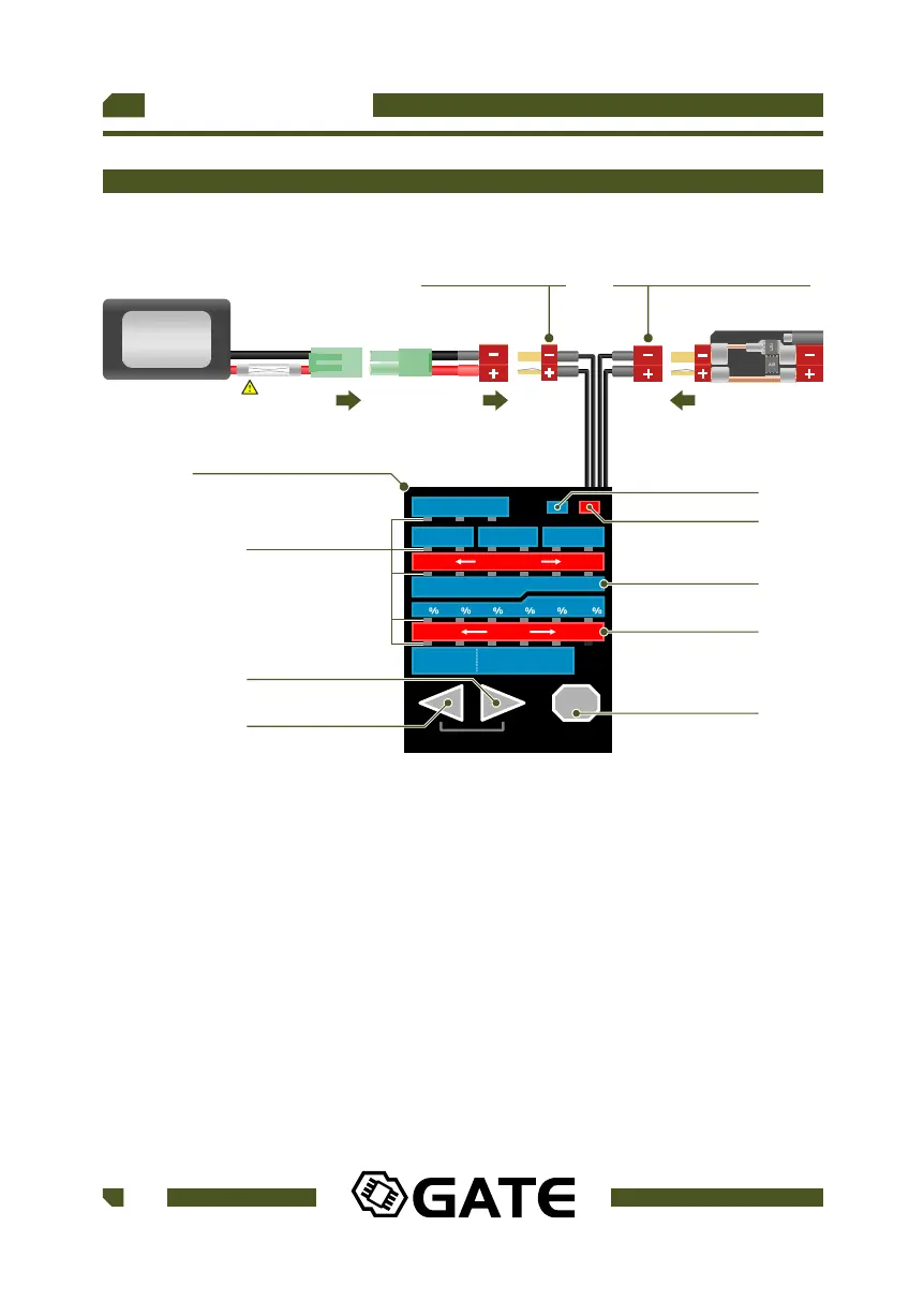
Fig 4.
50 60 70 80 90 100
SHORT LONG
BURST
TIME
STOCK WIRING MODIFIED WIRING
OFF TRIGGER AUTO
PRE-COCKING
BATTERY PROTECTION
ROF CONTROL
PRE-COCKING
BOOST
ACTIVE BRAKE
SMART TRIGGER
DARK MODE
OFF ON OFF ONOFF ON
7.4V 11.1V 14.8V 9.9V 13.2VOFF
LESS MORE
NEXT
LOAD DEFAULT
DEMO
SEMI
AUTO
SEMI
BURST
BURST
AUTO
SEMI
AUTO
SEMI
BURST
PROGRAMMING CARD
BATTERY CONNECTOR POWER MODULE CONNECTOR
BUTTON RIGHT
LEDs
BUTTON NEXT
RED DISPLAY
BLUE DISPLAY
BUTTON LEFT
RED ICON
BLUE ICON
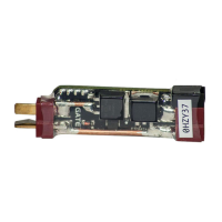
WARFET
BATTERY
UP TO 14.8V
Instructions:
1. Connect the battery to the Programming Card. The LEDs light on and start
blinking (Fig 4.).
2. Connect the WARFET Power Module to the Programming Card. All current
settings are displayed on the corresponding LEDs (Fig 5.).
3. When the BLUE ICON is on, check only on the blue display of the
Programming Card (Fig 5.).
When the RED ICON is on, check only on the red display of the Programming
Card (Fig 6.).
USER GUIDE
18
WWW.GATEE.EU
WARFET
FUSE