Guangcheng Technology GCAN-PLC user manual
The GCAN-PLC-510 can connect up to 32 distributed bus terminal
modules. When inserting the GC series terminal module, be sure to insert it
along the groove on the right side of the existing module sequentially until the
lock is stuck. When you assemble the nodes correctly, there is no obvious gap
between the terminal modules. If the modules are not assembled correctly, the
entire node will not operate normally.
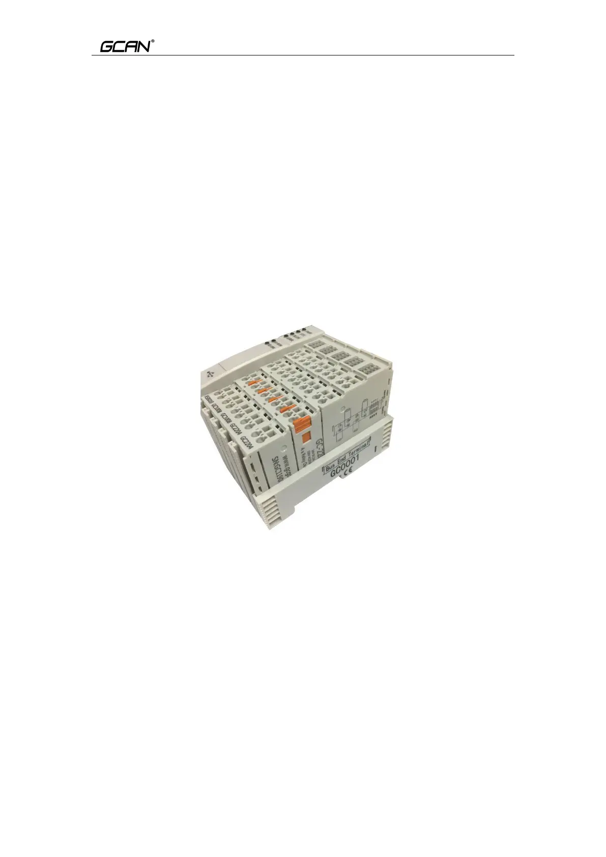
Please note: When using the GCAN-PLC-510 controller, you must ensure that
you have installed terminal modul at the right end of the entire node, and the
terminal resistance module has been fixed to the bottom without looseness, as
shown in Figure 2.4. This terminal module will ensure the data transmission
and power supply between GC series IO modules. The lack of this terminal
module or improper installation will cause errors in the entire system.
Figure 2.4 GC-0001 Terminal resistance module installation method
2.3 Wiring method
The power wiring as shown in figure 2.4. First, use a flat-blade
screwdriver to insert into the square hole, hold the top edge of the metal sheet
in the square hole, and press toward the hole. Then, insert the wire into the hole.
After plugging in, pull out the screwdriver and the wire can be firmly locked in
the hole.
 Loading...