g
GE
OPM_SGS_ISG_M22_M30_0US_V011.doc 25/38 Installation Guide
SG Series
225 & 300 kVA
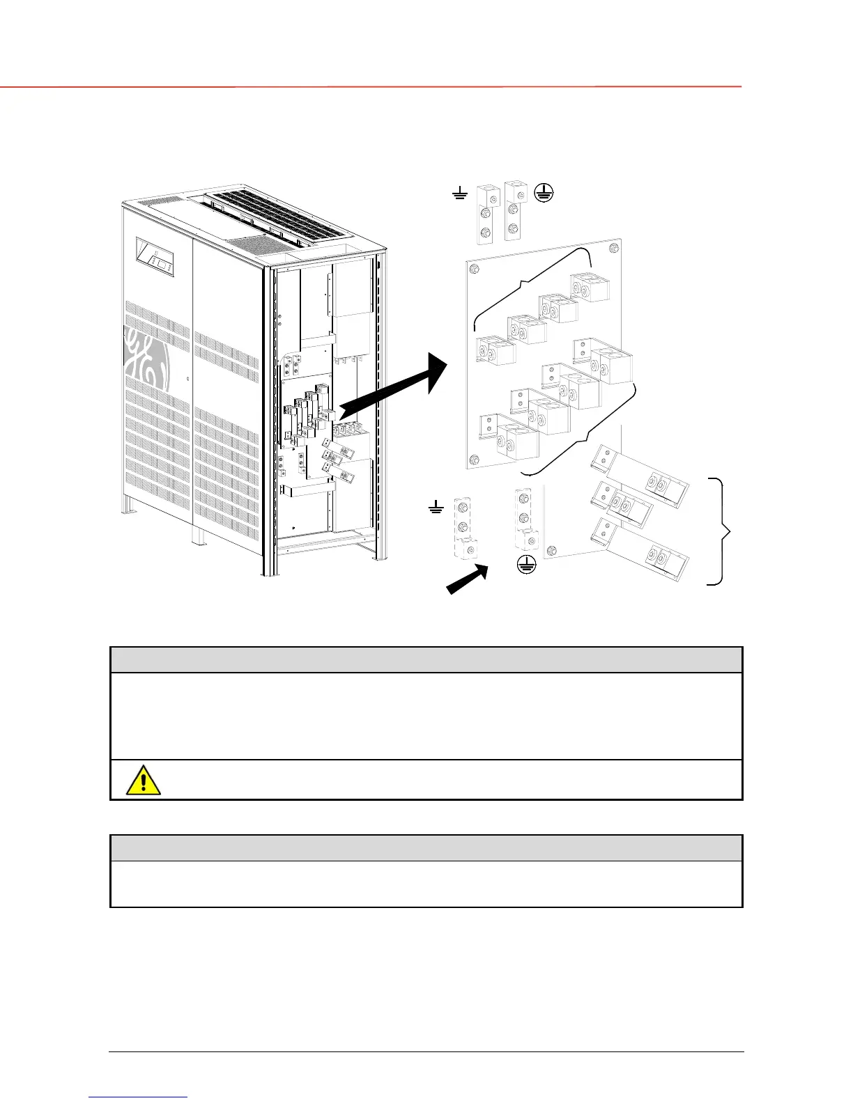
3.8.3 Power connection separate input utility
SGS_225-300_UPS connection separate_GE_01US
PE Load
PE
Input rectifier
Position of the PE compression lugs in case
the cable input is from the bottom of the UPS
Input rectifier
PE
PE Load
L1-2
L2-2
L3-2
2 - INPUT BYPASS
1
-
I
N
P
U
T
R
E
C
T
I
F
I
E
R
N
L3-1
L2-1
L1-1
L3
L2
L1
L
O
A
D
N
Fig. 3.8.3-1 Power connections Separate Input Utility
Separate Input Rectifier / Bypass
L1-1 Rectifier Phase A L1-2 Bypass Phase A
L2-1 Rectifier Phase B L2-2 Bypass Phase B
L3-1 Rectifier Phase C L3-2 Bypass Phase C
N Neutral (Bypass) PE Ground
The interconnection links BR1, BR2 and BR3 must be removed (see Fig. 3.8.3-2).
Output Load
L1
Load Phase A
L2
Load Phase B
L3
Load Phase C
N Neutral PE Ground
Bus bars BR1, BR2 and BR3 must be removed.
Cable terminations are to the Rectifier/Bypass Input Lugs and Load Output Lugs as shown above.
Connect wire to the Lugs using appropriate tools and appropriate torque.
Torque specification for Input/Output and DC power connections on Bus Bars: Section 3.8.1.