5
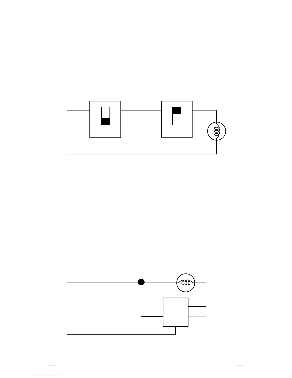
One of the ways to wire a two-switch/one-load circuit is to route the
incoming power through the first switch, then to the second switch
and then to the load. Although very common and by no means a
standard, it is the easiest to convert to Z-Wave control. With this
type of circuit, Switch 1 is replaced by the Z-Wave auxiliary switch
and Switch 2 is replaced with the primary Z-Wave switch. The auxil-
iary switch does not actually control the power; instead, it sends a
momentary voltage signal through the traveler wire to the primary
switch which in turn, controls the power to the load.
Typical 3-way circuit:
Please consult an electrician if you have trouble identifying the
type of wiring circuit you wish to convert or if you do not feel
confident in your ability to convert the circuit to Z-Wave control.
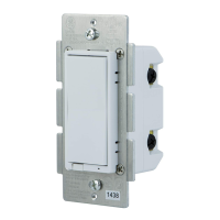
INSTALLATION
This switch may be used in new installations or to replace an
existing wall switch. It may be used by itself for 2-way control (one
switch & one load), with one 45610 Auxiliary Switch for 3-way con-
trol (two switches & one load) or with two 45610 Auxiliary switches
for 4-way control (three switches & one load). When used by itself
for 2-way control, please make sure that the screw terminal for
the traveler wire is insulated (Do Not Remove the tape over the
terminal if you are not using the traveler connection).
Single Switch Wiring Schematic
Black
White
Switch 1
Switch 2
Colored
(NOT GREEN)
Black Black
White (Neutral)
Z-Wave
45609
Black (Line/Hot)
Black
(Load)
Green (Ground)