7
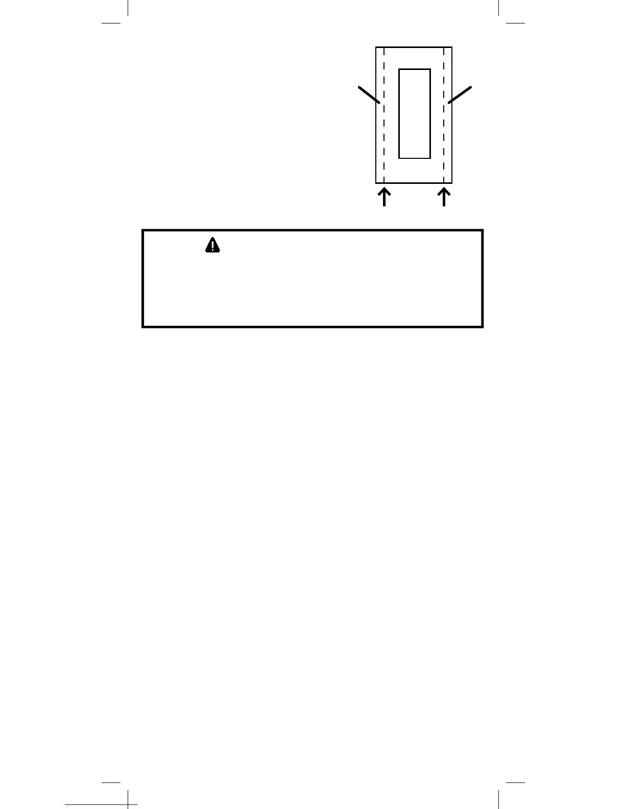
Single, Dual and Triple
Gang Boxes
When installing the 45609 in multiple
gang boxes it may be necessary to
break off one or both of the scored
tabs on the front yoke. This does
not affect the electrical rating of
the 45609.
WARNING - SHOCK HAZARD
Turn OFF the power to the branch circuit for the switch and
lighting fixture at the service panel. All wiring connections must
be made with the POWER OFF to avoid personal injury and/or
damage to the switch.
1. Shut off power to the circuit at fuse box or circuit breaker.
2. Remove wall plate.
! Warning: Verify power is OFF to switch box before continuing.
3. Remove the switch mounting screws.
4. Carefully remove the switch from the switch box. DO NOT
disconnect the wires.
5. There are five screw terminals on the 45609 switch; these are
marked LINE (Hot), Neutral, LOAD, GROUND and TRAVELER.
The Traveler terminal is only used for 3-way or 4-way wiring
and should remain insulated if the 45609 is being installed in
a 2-way system (one switch & one load). Match these screw
terminals to the wires connected to the existing switch. (Do
Not remove the tape over the terminal if you are not using the
traveler connection).
6. Disconnect the wires from the existing switch.
7. Connect the green or bare copper ground wire to the GROUND
terminal.
8. Connect the black wire that goes to the light to the terminal
marked LOAD.
9. Connect the black wire that comes from the electrical service
panel (Hot) to the terminal marked LINE.
10. Connect the white wire to the neutral terminal.
Note: UL specifies that the tightening torque for the screws
is 14Kgf-cm.
TabsTabs
Break at this line