Modifications reserved Page 27/99
OPM_SPE_XXX_10K_40K_8GB_V020.doc Operating Manual SitePro 10-15-20-30-40 kVA / S8
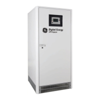
Included in the delivery packing are the air inlet grids, which must be mounted on the 4 sides at the
bottom of the cabinet with the screws included in the accessory bag.
If necessary, the terminal with the sensor must be mounted in the battery enclosure or cabinet (not in
contact with metallic parts) and the J3 plug must be connected to ”P1 - Power Interface” (see Section
5.8.2).
When the sensor is disconnected, the floating voltage is calibrated for temperature = 20°C.
If the battery cabinet is not mounted side by side the UPS, the cable connecting the temperature
sensor to the UPS should be run in a protective trunk or conduit.
NOTE !
If the battery distance from the UPS is >5 m, we suggest do not use this circuit
and the correct loading voltage must be installed manually according to the
annual average temperature at which the battery will be working (request
instructions to Service Centre or battery supplier).
For Parallel Systems, the delivery also includes the bus control cables for inter-
connecting the UPS modules.
Packing material recycling
GE, in compliance with environment protection, use only environmentally friendly
material.
UPS packing materials must be recycled in compliance with all applicable
regulations.
 Loading...


