Modifications reserved Page 40/99
OPM_SPE_XXX_10K_40K_8GB_V020.doc Operating Manual SitePro 10-15-20-30-40 kVA / S8
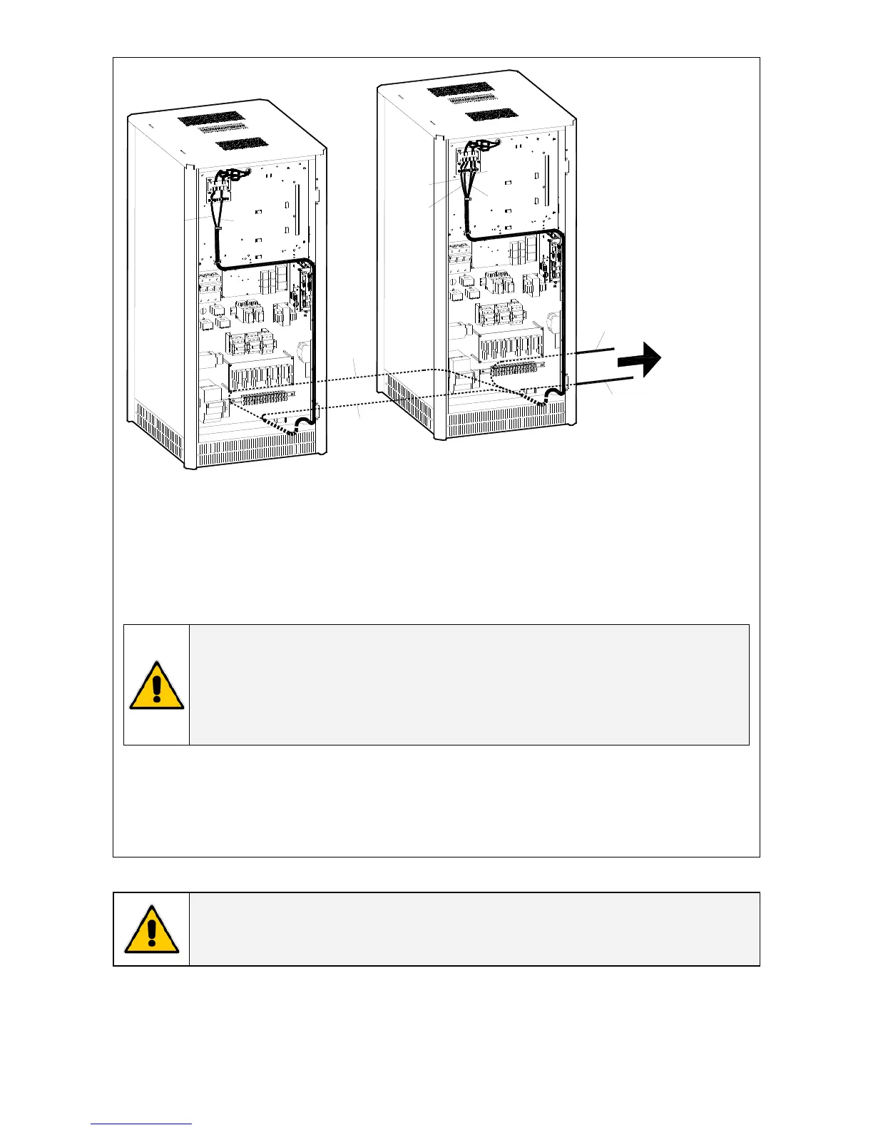
SP_010-040_S6_RPA control bus location_02GB
JA-1
JB-1
JA-1
JB-1
JA-2
JB-2
N
e
xt p
ar
al
l
el
un
i
t
UPS
2
JB-2
JB-1
JA-1
JA-2
UPS
1
Fig. 5.9.3-4 Control Bus cable routing and connection
Control bus cables routing
Place and fix the cables JA-1/2/3/4/5/6/7 and JB-1/2/3/4/5/6/7 inside the UPS cabinets in the
position illustrated in the drawing Fig 5.9.3-4.
NOTE !
Pay attention when cabling and routing the bus cables JA and JB inside the UPS
cabinet.
In case one unit should be removed from the Parallel System, the bus cables JA
and JB must be removed from the cabinet without disconnect them from the
metal plate where are located the sockets JA and JB.
For reliability reasons the cables JA-1/2/3/4/5/6/7 and JB-1/2/3/4/5/6/7 connecting the units should
be run in separated protected conduits (as indicated in Fig. 5.9.3-4) separated from the power
cables.
It is important that the cable JA must be the same length as cable JB.
WARNING !
Connection and commissioning of an additional UPS to an existing Parallel System,
must be performed by a service engineer from of your Service Centre.

 Loading...