Modifications reserved Page 79/99
OPM_SPE_XXX_10K_40K_8GB_V020.doc Operating Manual SitePro 10-15-20-30-40 kVA / S8
5. Open the manual bypass switch Q2 (Pos. 0) on all UPS units.
LED 9 (manual bypass Q2) is Off.
The load is supplied by the mains through the automatic bypass.
6.
Insert the inverter by pressing “Inverter ON” ( I ) key on first UPS unit.
The inverter will start up. LED 5 (inverter) must be blinking.
In a short time, when the inverter voltage is confirmed, the LED Inverter (5) will stop blinking and stay fixed
lit.
In case of sufficient output power, the output will transfer to Inverter.
LED Alarm turn Off and the LED Operation must be lit.
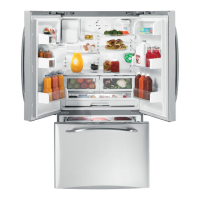
The synoptic diagram, on first UPS unit, must display the
status “LOAD SUPPLIED BY INVERTER”.
7.
Insert the inverter by pressing “Inverter ON” ( I ) key on all other UPS units.
Do not start the next Inverter until the sequence of the previous ends.
As soon as the output power of the inverters is sufficient to supply the load, the output of the units with
running inverter will transfer to inverter.
LED Alarm turn Off and the LED Operation must be lit.
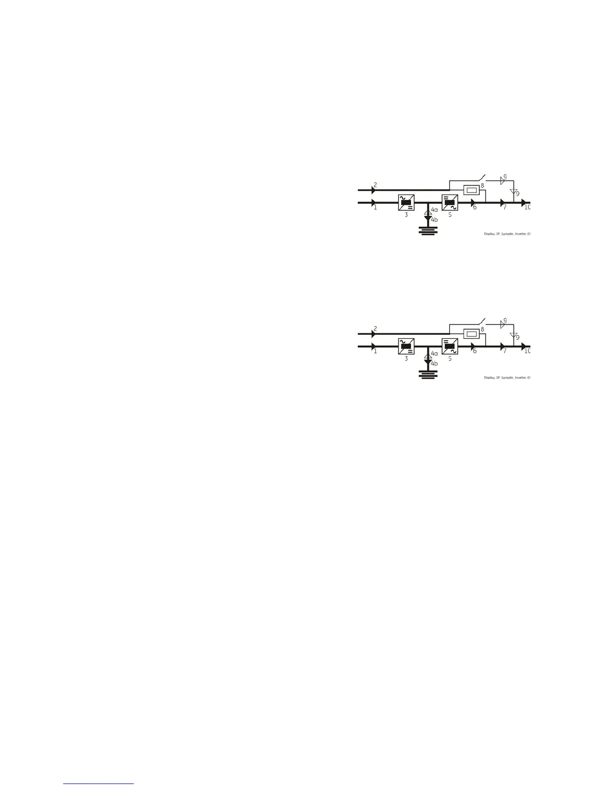
The synoptic diagram, on all UPS units, must display the
status “LOAD SUPPLIED BY INVERTER”.

 Loading...