Modifications reserved Page 82/99
OPM_SPE_XXX_10K_40K_8GB_V020.doc Operating Manual SitePro 10-15-20-30-40 kVA / S8
4.
Battery coupling to DC link on the Unit to reconnect.
After awhile, the green LED LD1 next to the battery fuse carrier, F8 – F9 lights up, indicating the rectifier
supplies the floating voltage.
After checking the right polarity, connect the battery to the DC-link by closing F8 – F9.
The battery is now connected to the DC link. LED 4b (charging battery) should be lit indicating battery charge.
5. Close output switch Q1 (Pos. I) on the Unit to reconnect.
LED Alarm is lit.
LED Operation must be lit.
6.
Insert the inverter by pressing “Inverter ON” ( I ) key on the Unit to reconnect.
The inverter will start up. LED Inverter (5) must be blinking.
Once inverter output voltage is OK, LED Inverter (5)
connected on the parallel bus bar sharing the load with each other’s.
LED Alarm turn Off.
LED Operation must be lit.
Verify on display screen that the load should be equally
shared between the parallel units.
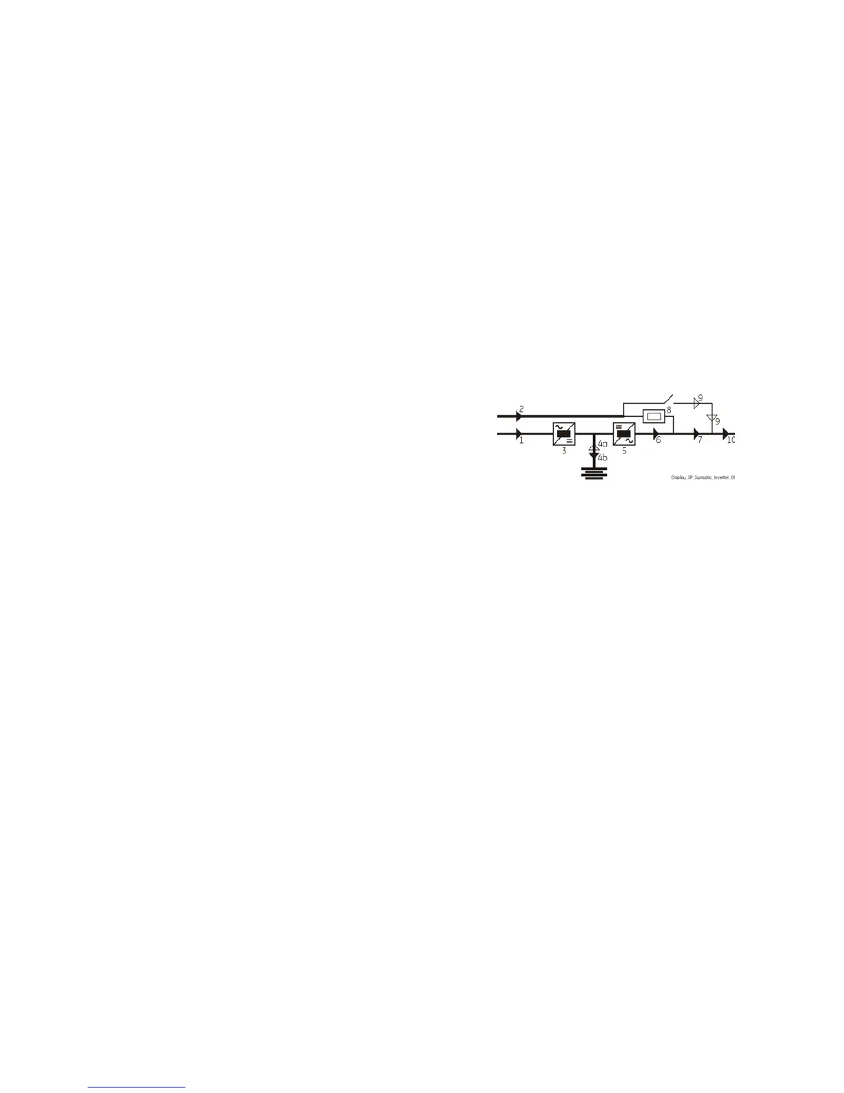
The synoptic diagram, on all UPS units, must display the
status “LOAD SUPPLIED BY INVERTER”.

 Loading...