6-2 869 MOTOR PROTECTION SYSTEM – COMMUNICATIONS GUIDE
CHAPTER 6: IEC 60870-5-104
By default the Object Information Address for the different data is as follows:
M_SP (Single Points) = 1000
M_ME (Measured value) = 2000
M_IT (Integrated Totals) = 3000
C_SC or C_DC (Single or Double Command) = 4000
P_ME_NB (Parameter of measured value) = 5000
Each Measured value has a Parameter of measured value (P_ME_NB) associated to its
threshold.
The IEC 60870-5-104 Deadbands settings are used to determine when to trigger
spontaneous responses containing M_ME_NB_1 analog data. Each setting represents the
threshold value for each M_ME_NB_1 analog point.
For example, to trigger spontaneous responses from the 869 when a current value
changes by
15 A, the “Analog Point xx Deadband” setting should be set to 15. Note that
these settings are the default values of the deadbands. P_ME_NB_1 (parameter of
measured value, scaled value) points can be used to change threshold values, from the
default, for each individual M_ME_NB_1 analog point. There are three ways to send the
measurands to the Master station. The measurands are part of the General Group and
Group 2, so when a general interrogation or group 2 interrogation takes place all the
measurands are included in the response. Also, there is a cyclic data period setting where it
is configured in the scan period to send the measurands to the Master. And the last way, is
by sending spontaneously when a deadband overflow takes place. The IEC104 Channels
sub-menu is shown below.
Commands are executed over the Binary Outputs. The first 8 Binary Outputs are
configured to receive Select/Operate Commands and the next 8 Binary Outputs are
configured to receive Direct Execute Commands.
Path: Setpoints > Device > Communications > IEC 60870-5-104
The IEC104 CHANNEL 1 PORT and IEC104 CHANNEL 2 PORT settings select the
communications port assigned to the IEC104 protocol for each channel. When this setting
is set to “Network - TCP”, the IEC104 protocol can be used over TCP/IP on channels 1 or 2.
The IEC104 NETWORK CLIENT ADDRESS settings can force the 869
to respond to a
maximum of two specific IEC104 masters which own the configured IP Addresses. The
settings in this sub-menu are shown below.
Path: Setpoints > Device > Communications > IEC 60870-5-104
Path: Setpoints > Device > Communications > IEC 60870-5-104
FAST PATH:
“IEC104 Channel 1 Port” takes the “Port Number 1” and “Client Address 1” to allow or reject
connections. The same method is used by channel 2.
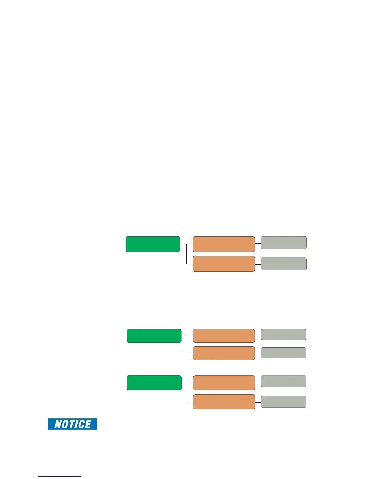
Message
Range: None, Network-TCP
■ IEC104 60870-5-104
■
CHANNEL 1
PORT: NETWORK-TCP
Range: None, Network-TCP
CHANNEL 2
PORT: NETWORK-TCP
Message
Range: standard IP address
■ IEC104 60870-5-104
■
CLIENT ADDRESS 1:
0.0.0.0
CLIENT ADDRESS 2:
0.0.0.0
Range: standard IP address
Message
Range: 1 to 65535 in steps of 1
■ IEC104 60870-5-104
■
TCP PORT NUMBER 1:
2404
TCP PORT NUMBER 2:
2404
Range: 1 to 65535 in steps of 1

 Loading...


