EasyManua.ls Logo

GE Advantium 240 User Manual

GE Advantium 240
53 pages
To Next Page IconTo Next Page
Page #1 background imageLoading...
Page #1 background image
– 1 –
GE Appliances
General Electric Company
Louisville, Kentucky 40225
31-9173
Advantium 240
Technical Service Guide
JULY 2008
GE Consumer & Industrial
SPEED
COOK
CUSTOM
SPEED COOK
CONV
BAKE
WARM
COOK
DEFROST
OVEN LIGHT
EXPRESS
REHEAT
START
CLEAR
LOCK/UNLOCK
HOLD 5 SECONDS
BACK
POWER
HELP
OPIONS
FAVORITE
RECIPES
TIMER
T
U
R
N
T
O
S
E
L
E
C
T
P
R
E
S
S
T
O
E
N
T
E
R
OVEN DEMO LOCKED TURN DIAL REM MUTE TIMER
OVEN MICROWAVE
BROIL
PROOF
TEMP
PAUSE
OFF
PSB2200NWW
PSB2200NBB
PSB2201NSS
ZSC2200NWW
ZSC2200NBB
ZSC2201NSS
ZSC2202NSS
https://appliancetechmanuals.com
Question and Answer IconNeed help?

Do you have a question about the GE Advantium 240 and is the answer not in the manual?

GE Advantium 240 Specifications

General IconGeneral
BrandGE
ModelAdvantium 240
CategoryOven
LanguageEnglish

Summary

Nomenclature

Model and Serial Number Interpretation

Explains model number structure and serial number date interpretation for Advantium ovens.

Introduction and Features

Advantium Oven Features and Benefits

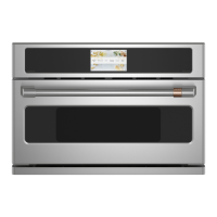
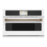
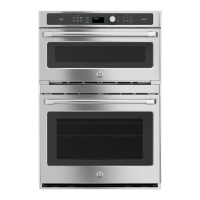
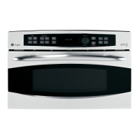
Lists and describes key capabilities, advantages, and user benefits of the Advantium oven.

Control Features

Control Panel Operation and Buttons

Explains the function of each button and the selector dial on the oven's control panel.

Speed Cook System Operation

Speed Cook Components and Overview

Describes heating elements, microwave, sensor cooking, and power level adjustments for Speed Cook.

Oven Operation and Compensation

Voltage, Thermal Compensation, and Proof Feature

Details how cooking time/power adjusts for voltage/temperature, and the proofing mode.

Installation Procedures

Installation Planning and Requirements

Covers planning, cutout dimensions, electrical needs, and cabinet considerations for installation.

Component Identification and Access

Component Locator Views

Identifies internal components from various views and the control panel assembly.

Component Access Chart

Lists oven components and their accessibility for service.

Control Boards Servicing

Power, Relay, Control, and Display Boards

Details connections and functions of key circuit boards and their interconnections.

Major Component Removal

Oven Removal Procedure

Step-by-step guide to safely remove the oven from its installation.

Disassembly of Covers, Panels, and Doors

Instructions for removing outer covers, access panels, control panel, and doors.

Component-Specific Servicing

Circuit Boards, Transformer, and Selector Board Servicing

Steps for removing power/relay boards, LVT, and selector board.

Heating Elements, Motors, Sensors, and Filters

Details servicing for lights, filters, transformer, magnetron, damper, blower, heaters, motors, sensors.

Diagnostics and Testing

Troubleshooting, Leak Testing, and Failure Detection

Provides a flowchart for faults, microwave leakage tests, and sensor/keypanel failures.

Service Test Mode Operation

Instructions for entering and running diagnostic tests on the oven.

Schematics and Warranty

Schematics and Wiring Diagrams

Presents the main circuit schematic and wiring diagrams for the oven.

Warranty Coverage

Outlines the limited one-year and five-year warranties for the product.

Related product manuals