·2. Mount the device as
described
under
re-
placement and
insert
the pin which couples the
connecting
rod
and the
trip
paddle.
3.
Olos~ the
breaker
and
insert
a feeler
gage
1/32
in. thick between the
armature
and
magnet. . This should
be done
from
. the
rear
of the
breaker.
The
feeler
gage should be
no
. wider · than
1/2
in. and
at
least
4 inches long.
. ·
4.
Close the
armaµire
agailµit the gage and
magnet. ·
5.
· If the
breaker
does not
trip,
form
paddle
14
to obtain positive
trip.
· .
6.
Check visually to make
sure
that the
connecting
rod
does not
restrict
the
engagement
of the
breaker
trip
latch
when the
breaker
mech-
anism
resets.
·
It
should always
be
possible to
adjust
its
lelllrth to a
DOint
where
resetting
is
not interf
erred
with and
yet
positive tripping by
thA
overcurrent
device
is
achieved.
SERIES
OVERCURRENT
"TRIPPING
DEVICE
EC•1
··
(Fig.
27)
Each
series
overcurrent
tripping device
is
enclosed
in
a molded
case
and mounted
by
three
screws
and a
bracket
to the
lower
part
of the ·
pole
~t
}?ase.
The devic.e · can .
be
provided with the same
tripping combinations
as
the
EC~.1
direct
acting
-device.
SHORT
TIME-DELAY
TRIPPING
(Fig. 27) . . .
. The
armature
(7)
is
restrained
by
cali-
brating
spring
(8). After the magnetic force
produced by
an
overcurrent
·
conc:Ution
overcomes
~
this
restraining
force; the ·
armature
movement
is
further
·
retarded
by an escapement mechan- .
ism
which produces
an
-inverse .
time
delay char~
acteristic.
The mechanism
is
shown on Fig.
27.
. . - . .
LONG
TIME-DELAY
TRiPPING
. .
(Fig. 27) · . · . . ·
The
armature
(10)
is
restrained
by the· calib-
ratio~ spring (11). · After the magnetic force
produced by an
overcurrent
condition
overco~es
this
restraining
force, the
armature
movement
·
is
further
retarded
by the flow of silicone oil .
in a dashpot, which produces an inverse time
delay·
characteristic.
The· mechanism
is
shown
on Fig. 27.
INSTA~TAN
.
EOUS
TRIPPING
{Fig. 27).
·
(a)
Adjustable instantaneous tripping takes place
after
the magnetic
force
produced by an
over-
current
condition, overcomes. the restrainingforce
of the calibration
spring
. which
can
be
adjusted
by
the calibration clamp nut (14). .
(b)
· Non-adjustable instantaneous tripping takes
place
after
the magnetic
force
produced
by
an
overcurrent condition
overco~es
the restraining
Low Voltage Power Circuit
Breakers
GEK-7303
force of a non-adjustable spring.
.
ADJUSTMENTS
(Fig.
27)
Calibration clanu>ing nuts (14)
are
used to
set
the desired pickup
tor
..
the adjustable elements.
. .
. To adjust
for
approximately
1/32
in.
over-
travel
of
trip
arm
(19)
after
tripping:
1. Check trip latch ·engagement. See
AD-
JUSTMENTS
- OPERA
TING
MECHANISM.
2.
Loosen the locknut• and
turn
the adjusting
screw
(9)
on
the
trip
arm
(19). The
screw
should
not touch the
trip
paddle when the .
breaker
is
"open". Adjust positive
trip
same
as EC-2A
(See page
33 ). ·
3.
Tighten the adjusting
screw
locknut•
on
the
trip
arm.
•
NOTE:
In
Ueu
of loclmuts, some devices
are
equipped with self-locking nylon
insert
nuts.
REPLACEMENT
(Fig. 27)
.
1. Remove front
frame
(see
SEPARATION
·
OF
FRONT
AND
REAR
FRAMES).
2.
Remove the bolts holding the coil to the
-lower stud.
3. Remove
bracket
. and mounting screws.
.
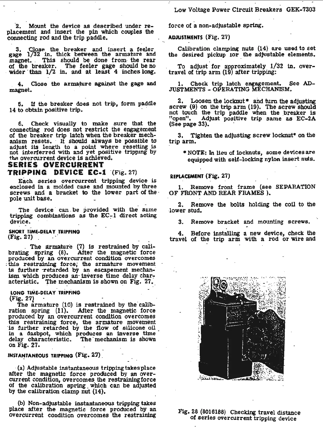
4.
· Before
installing
a new device, check the
travel
of the
trip
arm
with a
rod
or
wire and
Fig.
28
(8016188)
Checking
travel
distance
of
series
overcurrent tripping device
 Loading...


