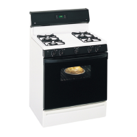
Installation Instructions
GAS PIPE AND ELECTRICAL OUTLET LOCATIONS
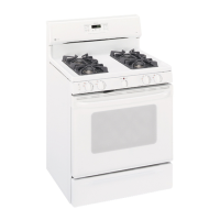
For models JGB500, PGB900, PGB908 and PGB910 onlg.
(See the below section for models
JGB605, PGB916, PGB918 and PGB975.) /,7
3F'
Recommendedarea for 120Voutlet
on rear wall and area for through-
the-wall connection of pipestub
and shut-off valve.
\
Recommendedarea for
through-the-floor
connection of pipestub
and shut-off valve.
GAS PIPE AND ELECTRICAL OUTLET LOCATIONS
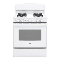
For models JGB605, PGB916,
PGB918 and PGB975 only.
(See the above section for models
30"
JGB500, PGB900, PGB908 and PGB910.)
Recommendedarea for 120V
outlet on rear wall and area for
through-the-wall connection
of pipe stub and shut-off valve.
Recommendedareafor "_
through-the-floor connection
of pipe stub andshut-off valve.
45