31-5000275 Rev. 5 13
Step 3 - Installation of the Outdoor Unit (Cont.)
Installation Instructions
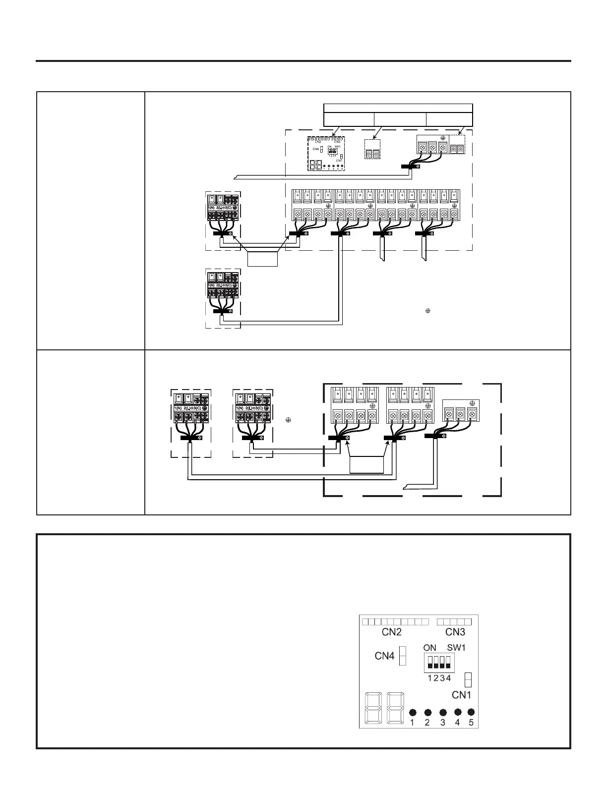
D. Wiring Error Check
• This unit is capable of automatically checking for wiring errors
between the indoor and outdoor units.
• To enter the wiring error check test, remove power to unit,
place all 4 DIP switches on the test board in the “ON” position
(illustration 6). Reapply power to the unit. The system will now
enter “Wiring Error Check”
• The numeric display will initialize and begin to alternate
between the compressor working frequency (a number
representing the Hz value) and “CH” (Checking).
• As the check is being performed, all units that are properly
connected will be indicated by the corresponding LED for that
circuit being lit constantly. (LED 1 = piping circuit A, LED 2 =
piping circuit B, ...)
• After the check has completed, if all wiring is correct,
the numeric display will indicate “0” and the single LEDs
representing the individual circuits for the connected indoor
units will be lit constantly.
• If there are any miswired units, the numeric display will flash
“EC” (error connection), and th corresponding LED for the
miswired circuit will flash. Check and correct the wiring as
needed.
• Refer to the chart shown below. (Table 2)
• When the test is complete, remove power to the system and
return the 4 DIP switches to the OFF position. Reapply power
to the the system. The test is complete.
• If the self-check is not possible, check the indoor unit wiring
and piping in the usual manner.
Outdoor unit
Power Wiring
3
2
1
)
(
N
)
(L
)
(
C
2
1
)
(
N
)
(
L
Indoor unit A
Control Wiring
4 Wire - 14 AWG
Stranded
43
43
To Service Disconnect
1
2
3
=White
=Black
=Red
=Green
A B C D
Sugested Colors
230 Volt Supply. 1 to L1, 2 to L2.
Indoor unit B Indoor unit C Indoor unit D
3
2
1
)
(
N
)
(L
)
(
C
3
2
1
)
(
N
)
(L
)
(
C
3
2
1
)
(
N
)
(L
)
(
C
Strain Relief
Brackets
Only on FlexFit 3U & 4U
and Arctic 2U & 3U
Only on FlexFit 4U
and Arctic 2U & 3U
Only on FlexFit 3U
Diagnostic and Control
Models: ASH436JCDS*
ASH324NCDW*
ASH324JCDS*
ASH220NCDW*
ASH436NCDW*
Models: ASH218JCDS*
Outdoor unit
Power Wiring
3
2
1
)
(
N
)
(L
)
(
C
3
2
1
)
(
N
)
(L
)
(
C
Indoor unit 2
Control Wiring
4 Wire - 14 AWG
Stranded
To Service Disconnect
1
2
3
=White
=Black
=Red
=Green
Sugested Colors
230 Volt Supply. 1 to L1, 2 to L2.
Indoor unit 1
2
1
)
(
N
)
(
L
Strain Relief
Brackets
Only on ASH324J*,
ASH436J*, ASH220N*,
ASH324N*, and ASH436N*
Only on ASH436J*,
ASH220N*, ASH324N*, and
ASH436N*
Only on ASH324J*
 Loading...