16 31-5000275 Rev. 5
Step 4 - Final Check
System Test
Please explain to the customer how to operate the
system by using the Owner’s Manual found with the
indoor unit.
Check Items for Test Run
No gas leak from linesets?
Are the linesets insulated properly?
Are the connecting wirings of indoor and outdoor firmly
inserted to the terminal block?
Is the connecting wiring of indoor and outdoor fixed?
Is condensate draining correctly?
Is the ground wire securely connected? Is the indoor unit
securely fixed?
Is power source voltage correct according to local code?
Is there any odd noise?
Does the cooling temperature drop between 20-30°F?
Does the heating temperature raise between 35-40°F?
Is the room temperature display accurate?
Explaining Operation To the End User
• Using the Owner’s Manual, explain to the user how
to use the heat pump, (the remote controller, adding/
removing the air filters, placing or removing the
remote controller from the remote control holder,
cleaning methods, precautions for operation, etc.)
• Review precautions for operation.
• Recommend that the user read the Operating
Instructions carefully.
Step 3 - Installation of the Outdoor Unit (Cont.)
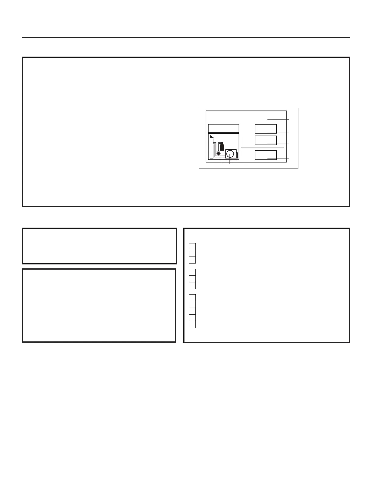
H. Refrigerant Charging
• Add any additional refrigerant after evacuation using a
digital scale.
NOTE: Charge liquid only.
• Fill out the refrigerant charge label using indelible ink.
• Place the factory refrigerant charge found in table on
page 14.
• Place the amount of additional refrigerant added in box
number 2.
• Add boxes 1 and 2 together and place the value in the
sum box (D).
• Adhere the filled out label in the proximity of the
product charging port and under the outside unit valve
cover.
• If no sticker found, write amounts on outdoor unit with
permanent marker above the charging port.
• Remove the cap from the liquid line valve. Using a
hex wrench, open the valve, then replace and tighten
the cap securly to avoid leaks.
• Remove the cap from the suction line valve. Using a
hex wrench, open the valve, then replace and tighten
the cap securly to avoid leaks.
• Wrap the line set, drain line, and 14/4 AWG wiring
starting at the bottom of the bundle with an overlap
type wrap until you reach the piping hole.
• Use a sealant to seal the piping hole opening on both
sides of the wall in order to prevent drafts, weather, or
pests from entering the building.
This product contains fluorinated greenhouse gases
covered by the Kyoto Protocol. Do not vent into the
atmosphere.
1
1+2=
oz
R410A
2
oz
2=
1=
B
C
D
F E
oz
A
Contains fluorinated greenhouse gases
covered by the Kyoto Protocol
Refrigerant type: R-410A
GWP* value: 2088
GWP = global warming potential
Installation Instructions
 Loading...