Section 13 - ALERT RELAY ACTUATION CIRCUITS
23
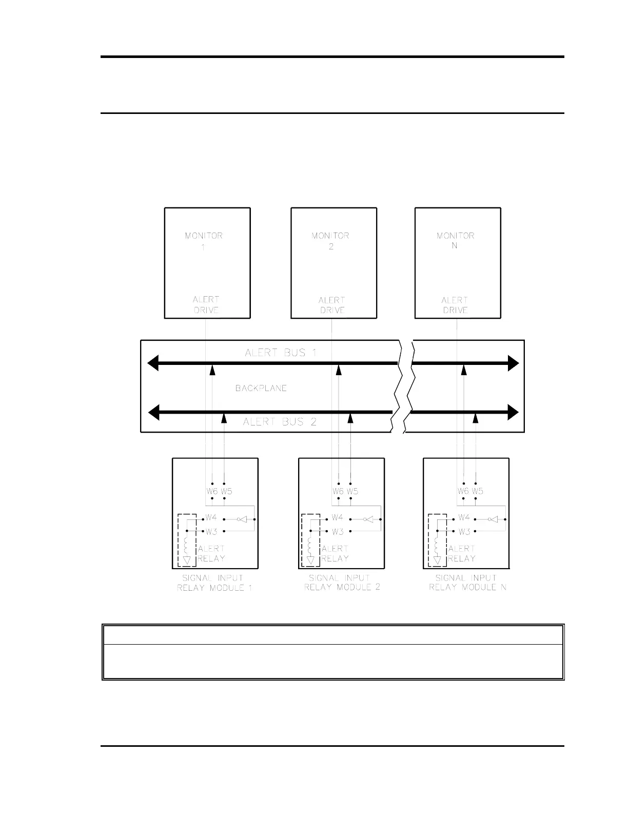
13. ALERT RELAY ACTUATION CIRCUITS
The following diagram shows the functional concept of jumper configurations for Alert relay
bus actuation for the Dual Relay Module. For more detail refer to schematics in the
applicable monitor manuals.
NOTE: The relay located directly behind a monitor is always driven by that monitor,
and all other relays connected on the same bus will also be driven by that
monitor.
CAUTION
The following information is not applicable to the Velomitor. Refer to the 3300/55
Maintenance Manual for jumper configuration of the Velomitor Relay Module.
 Loading...


