Section 13 - ALERT RELAY ACTUATION CIRCUITS
25
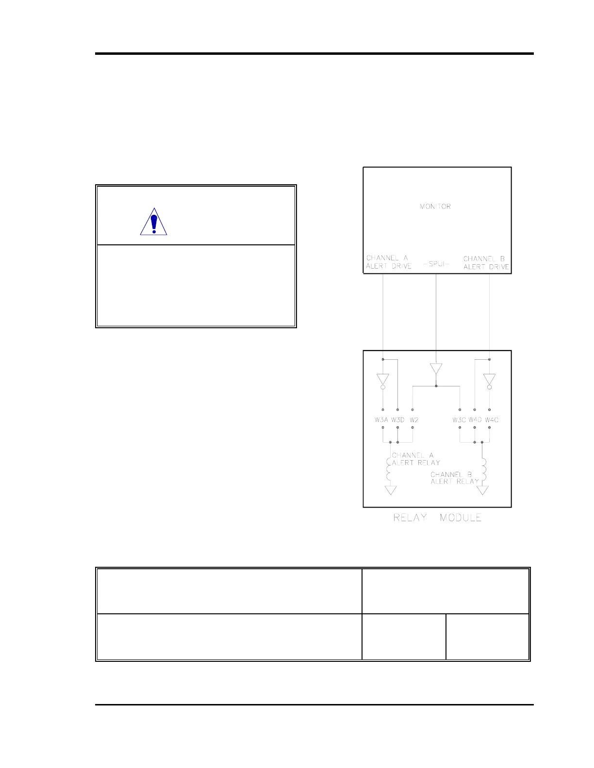
The following diagram shows the functional concept of jumper configurations for Alert relay
actuation for the Quad Relay Module. Note: The jumper configuration shown is not
applicable to the Velomitor Signal Input Relay Module. Refer to the Dual Velocity Monitor
Maintenance Manual. For more details refer to schematics in the applicable monitor
manuals.
CAUTION
The following information is not
applicable to the Velomitor. Refer to
the 3300/55 Maintenance Manual for
jumper configuration of the Velomitor
Relay Module.
FUNCTION
JUMPER
INSTALL REMOVE
Set Alert relays for normally energized operation
Set Alert relays for normally de-energized operation
W3A,4C
W2,3C,3D,4D
W2,3C,3D,4D
W3A,4C
 Loading...


