10
4.11.1 Switch Alignment and Adjustment Procedure
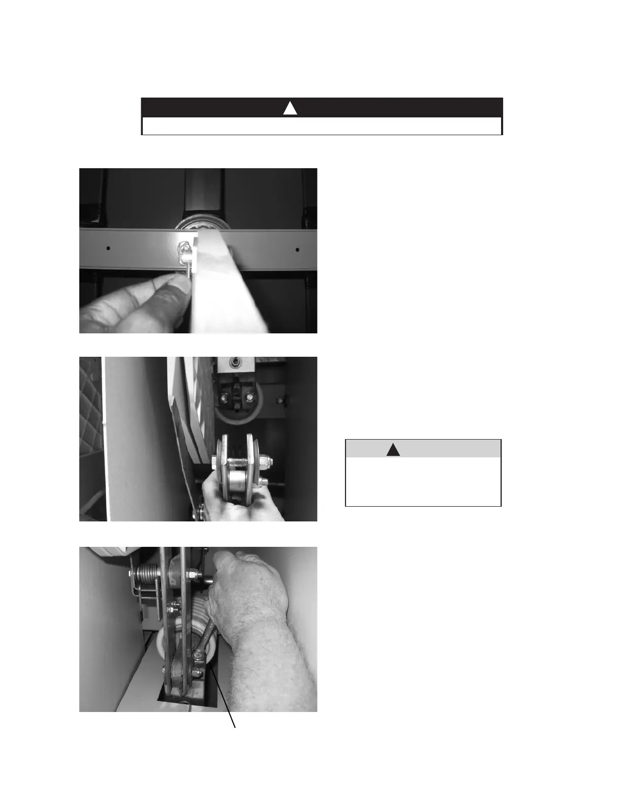
Step 1: Disconnect Pushrods
Remove cotter pins and clevis pins that connect
pushrods to operating arms of each pole of switch.
See Figure 5.
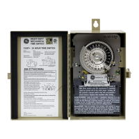
Step 2: Main Blade Alignment
Disengage switch blades by pulling outward on
the main switch blade until the main blades are
separated from the jaw casting. Continue to pull
outward until arcing blade disengages from the
arc chute. See Figure 6.
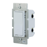
If the main blades do not align with the jaw
contacts, loosen the hinge casting mounting bolts
and move the pole assembly. Then re-tighten the
bolts. See Figure 7.
F
igure 5
Figure 6
Figure 7
DANGER
M
ake sure that all power sources are deenergized before attempting any maintenance.
!
WARNING
The arcing blade is under spring
pressure and snaps open when clear of
the stationary arcing contacts within
the arc chute.
!
Hinge casting
BreakMaster Load Interrupter Switch