12
Step 4: Hinge Contact Pressure Adjustment
Open the switch until the arcing blade just clears
the arc chute. Connect a spring scale to the main
b
lades approximately 1
1
⁄2”
below the jaw contact.
S
ome switches are equipped with a spacer just
b
elow the jaw. This provides a convenient point to
connect the scale. On other switches, use a “tee”
adapter allowing equal force on both blades. See
Figures 11, 12, and 13.
A force of 2-4 pounds should be necessary to
move the blades. Loosen or tighten the hinge bolt
as necessary to meet the 2-4 pound requirement.
Step 5: Jaw Contact Pressure Adjustment
Close each switch pole and connect a spring
scale as described in Step 4. A force of 30-36
pounds should be necessary to open the switch
blades. Loosen or tighten the jaw contact bolts
as necessary to meet the 30-36 pound require-
ment
. See Figur
es 11, 12, and 13 for spring scale
placement.
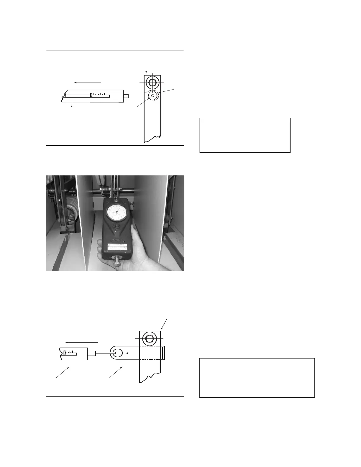
Pull 30 to 36 pounds
Scale 50-pound range
A
luminum Bar
Scale Hook
Switch Blades
600A Switches
Figure 11
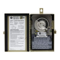
Figure 12
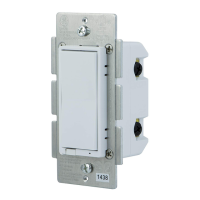
Pull 30 to 36 pounds
Scale Adapter
Switch Blades
Figure 13
NOTE
If the nylon insert locknut is removed
for any reason, it must be replaced
with an "ESNA" stopnut.
NOTE
Spring scale referenced in Steps 4 and 5 should
be Chatillon model# IN-10MRP for force range
10 lbs. 4 oz. or Chatillon model# IN-50MRP for
force range 50lbs. 8oz. or equivalent.
BreakMaster Load Interrupter Switch