GE Multilin C60 Breaker Protection System 5-51
5 SETTINGS 5.2 PRODUCT SETUP
5
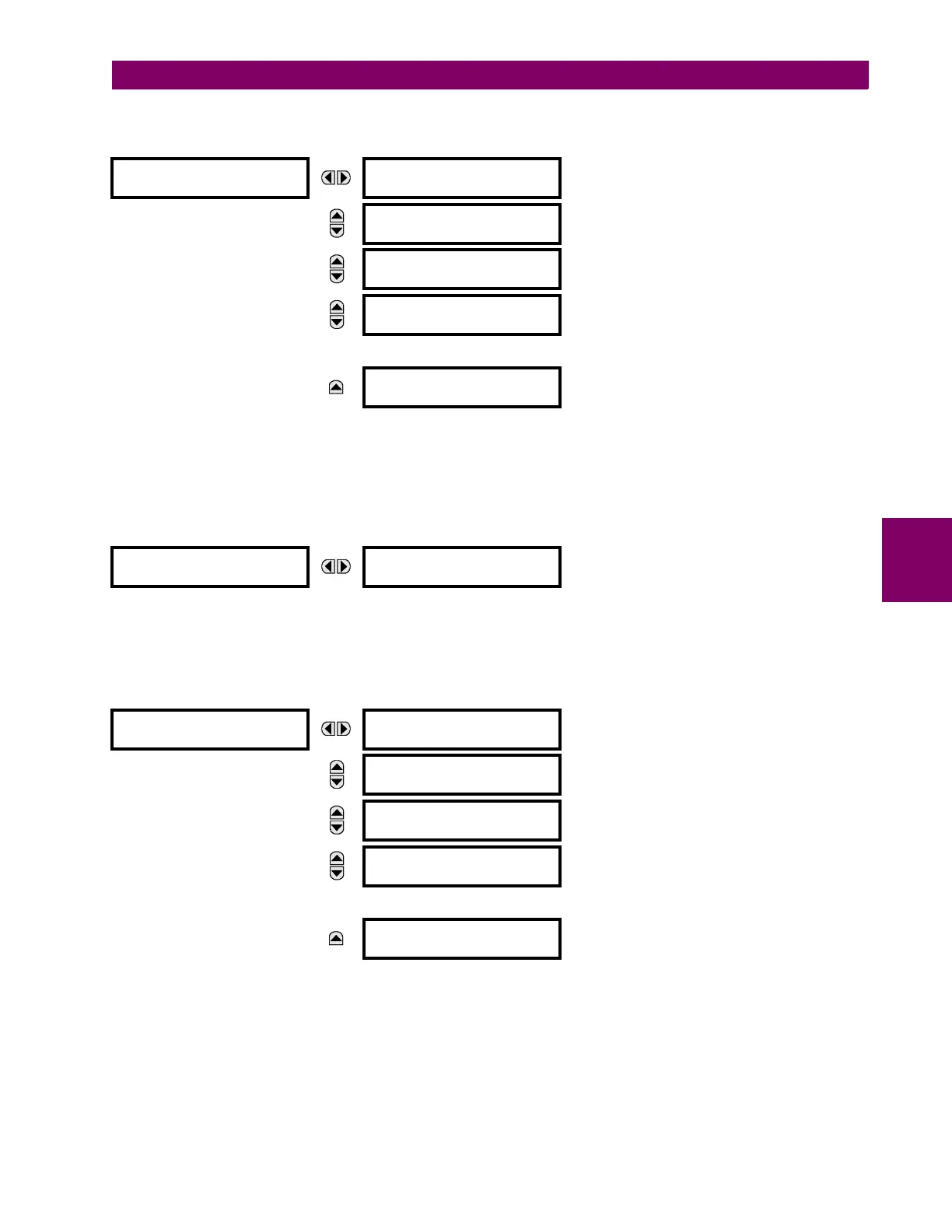
The GGIO1 status configuration points are shown below:
PATH: SETTINGS PRODUCT SETUP COMMUNICATIONS IEC 61850 PROTOCOL GGIO1 STATUS CONFIGURATION
The NUMBER OF STATUS POINTS IN GGIO1 setting specifies the number of “Ind” (single point status indications) that are
instantiated in the GGIO1 logical node. Changes to the NUMBER OF STATUS POINTS IN GGIO1 setting will not take effect until
the C60 is restarted.
The GGIO2 control configuration points are shown below:
PATH: SETTINGS PRODUCT SETUP COMMUNICATIONS IEC 61850 PROTOCOL GGIO2 CONTROL CONFIGURATION
GGIO2 CF SPSCO 1(64)
The GGIO2 control configuration settings are used to set the control model for each input. The available choices are “0”
(status only), “1” (direct control), and “2” (SBO with normal security). The GGIO2 control points are used to control the C60
virtual inputs.
The GGIO4 analog configuration points are shown below:
PATH: SETTINGS PRODUCT SETUP COMMUNICATIONS IEC 61850 PROTOCOL GGIO4 ANALOG CONFIGURATION
The NUMBER OF ANALOG POINTS setting determines how many analog data points will exist in GGIO4. When this value is
changed, the C60 must be rebooted in order to allow the GGIO4 logical node to be re-instantiated and contain the newly
configured number of analog points.
GGIO1 STATUS
CONFIGURATION
NUMBER OF STATUS
POINTS IN GGIO1: 8
Range: 8 to 128 in steps of 8
MESSAGE
GGIO1 INDICATION 1
Off
Range: FlexLogic operand
MESSAGE
GGIO1 INDICATION 2
Off
Range: FlexLogic operand
MESSAGE
GGIO1 INDICATION 3
Off
Range: FlexLogic operand
↓
MESSAGE
GGIO1 INDICATION 128
Off
Range: FlexLogic operand
GGIO2 CF SPCSO 1
GGIO2 CF SPCSO 1
CTLMODEL: 1
Range: 0, 1, or 2
GGIO4 ANALOG
CONFIGURATION
NUMBER OF ANALOG
POINTS IN GGIO4: 8
Range: 4 to 32 in steps of 4
MESSAGE
GGIO4 ANALOG 1
MEASURED VALUE
MESSAGE
GGIO4 ANALOG 2
MEASURED VALUE
MESSAGE
GGIO4 ANALOG 3
MEASURED VALUE
↓
MESSAGE
GGIO4 ANALOG 32
MEASURED VALUE