GE Multilin C60 Breaker Protection System 5-91
5 SETTINGS 5.2 PRODUCT SETUP
5
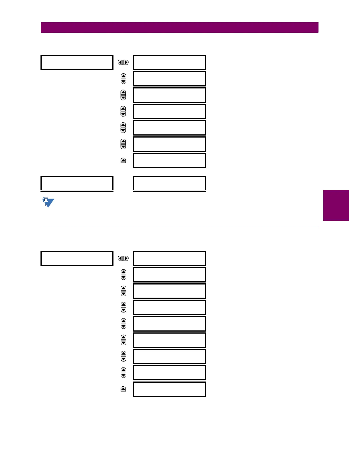
An example user display setup and result is shown below:
If the parameters for the top line and the bottom line items have the same units, then the unit is displayed on the
bottom line only. The units are only displayed on both lines if the units specified both the top and bottom line items
are different.
5.2.17 DIRECT INPUTS AND OUTPUTS
a) MAIN MENU
PATH: SETTINGS PRODUCT SETUP DIRECT I/O
USER DISPLAY 1
DISP 1 TOP LINE:
Current X ~ A
Shows user-defined text with first tilde marker.
MESSAGE
DISP 1 BOTTOM LINE:
Current Y ~ A
Shows user-defined text with second tilde marker.
MESSAGE
DISP 1 ITEM 1:
6016
Shows decimal form of user-selected Modbus register
address, corresponding to first tilde marker.
MESSAGE
DISP 1 ITEM 2:
6357
Shows decimal form of user-selected Modbus register
address, corresponding to second tilde marker.
MESSAGE
DISP 1 ITEM 3:
0
This item is not being used. There is no corresponding
tilde marker in top or bottom lines.
MESSAGE
DISP 1 ITEM 4:
0
This item is not being used. There is no corresponding
tilde marker in top or bottom lines.
MESSAGE
DISP 1 ITEM 5:
0
This item is not being used. There is no corresponding
tilde marker in top or bottom lines.
USER DISPLAYS
→
Current X 0.850
Current Y 0.327 A
Shows the resultant display content.
DIRECT I/O
DIRECT OUTPUT
DEVICE ID: 1
Range: 1 to 16
MESSAGE
DIRECT I/O CH1 RING
CONFIGURATION: Yes
Range: Yes, No
MESSAGE
DIRECT I/O CH2 RING
CONFIGURATION: Yes
Range: Yes, No
MESSAGE
DIRECT I/O DATA
RATE: 64 kbps
Range: 64 kbps, 128 kbps
MESSAGE
DIRECT I/O CHANNEL
CROSSOVER: Disabled
Range: Disabled, Enabled
MESSAGE
CRC ALARM CH1
See page 5–97.
MESSAGE
CRC ALARM CH2
See page 5–97.
MESSAGE
UNRETURNED
MESSAGES ALARM CH1
See page 5–98.
MESSAGE
UNRETURNED
MESSAGES ALARM CH2
See page 5–98.