GE Multilin C60 Breaker Protection System 5-271
5 SETTINGS 5.8 INPUTS AND OUTPUTS
5
5.8.12 IEC 61850 GOOSE ANALOGS
PATH: SETTINGS INPUTS/OUTPUTS IEC 61850 GOOSE ANALOGS GOOSE ANALOG INPUT 1(32)
The IEC 61850 GOOSE analog inputs feature allows the transmission of analog values between any two UR-series
devices. The following settings are available for each GOOSE analog input.
• ANALOG 1 DEFAULT: This setting specifies the value of the GOOSE analog input when the sending device is offline
and the
ANALOG 1 DEFAULT MODE is set to “Default Value”.This setting is stored as an IEEE 754 / IEC 60559 floating
point number. Because of the large range of this setting, not all possible values can be stored. Some values may be
rounded to the closest possible floating point number.
• ANALOG 1 DEFAULT MODE: When the sending device is offline and this setting is “Last Known”, the value of the
GOOSE analog input remains at the last received value. When the sending device is offline and this setting value is
“Default Value”, then the value of the GOOSE analog input is defined by the
ANALOG 1 DEFAULT setting.
• GOOSE ANALOG 1 UNITS: This setting specifies a four-character alphanumeric string that can is used in the actual
values display of the corresponding GOOSE analog input value.
GOOSE Analogs are floating-point values, with no units. The GOOSE UNIT and PU base settings allow the user to
configure GOOSE Analog, so that it can be used in a FlexElement.
GOOSE Analogs that represent current, voltage, power, frequency, angles, or power factor can be used in a FlexEle-
ment. The following text must be used in the UNITS setting, to represent these types of analogs: A, V, W, var, VA, Hz,
deg, and no text (blank setting) for power factor.
GOOSE Analogs can be compared to other GOOSE Analogs with any character string or no string.
• GOOSE ANALOG 1 PU: This setting specifies the per-unit base factor when using the GOOSE analog input FlexAna-
log values in other C60 features, such as FlexElements. The base factor is applied to the GOOSE analog input Flex-
Analog quantity to normalize it to a per-unit quantity. The base units are described in the following table.
The per-unit base setting represents thousands, not single units. For example, a PU base of 1.000 is actually 1000 and
a PU base of 0.001 is 1.
When using GOOSE Analogs and PU base in FlexElements, the largest value that can be displayed in the FlexEle-
ment actual values is 2,140,000.000.
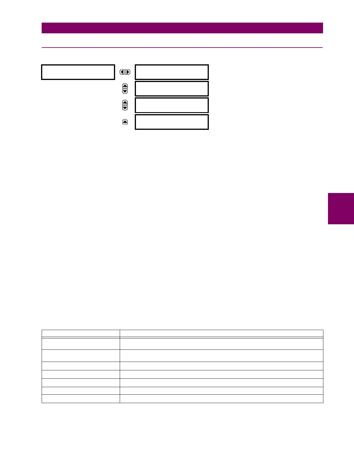
GOOSE ANALOG
INPUT 1
ANALOG 1 DEFAULT:
1000.000
Range: –1000000.000 to 1000000.000 in steps of 0.001
MESSAGE
ANALOG 1 DEFAULT
MODE: Default Value
Range: Default Value, Last Known
MESSAGE
GOOSE ANALOG 1
UNITS:
Range: up to 4 alphanumeric characters
MESSAGE
GOOSE ANALOG 1 PU:
1.000
Range: 0.000 to 1000000000.000 in steps of 0.001
Table 5–34: GOOSE ANALOG INPUT BASE UNITS (Sheet 1 of 2)
ELEMENT BASE UNITS
BREAKER ARCING AMPS
(Brk X Arc Amp A, B, and C)
BASE = 2000 kA
2
× cycle
dcmA BASE = maximum value of the
DCMA INPUT MAX setting for the two transducers configured
under the +IN and –IN inputs.
FREQUENCY f
BASE
= 1 Hz
PHASE ANGLE ϕ
BASE
= 360 degrees (see the UR angle referencing convention)
POWER FACTOR PF
BASE
= 1.00
RTDs BASE = 100°C
SOURCE CURRENT I
BASE
= maximum nominal primary RMS value of the +IN and –IN inputs