5-78 C60 Breaker Protection System GE Multilin
5.2 PRODUCT SETUP 5 SETTINGS
5
When testing is in progress, the LEDs are controlled by the test sequence, rather than the protection, control, and monitor-
ing features. However, the LED control mechanism accepts all the changes to LED states generated by the relay and
stores the actual LED states (on or off) in memory. When the test completes, the LEDs reflect the actual state resulting from
relay response during testing. The reset pushbutton will not clear any targets when the LED Test is in progress.
A dedicated FlexLogic operand, LED TEST IN PROGRESS, is set for the duration of the test. When the test sequence is initi-
ated, the
LED TEST INITIATED event is stored in the event recorder.
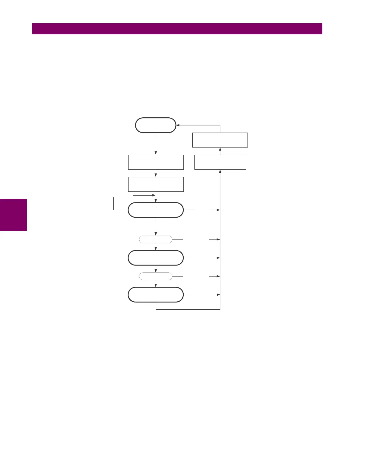
The entire test procedure is user-controlled. In particular, stage 1 can last as long as necessary, and stages 2 and 3 can be
interrupted. The test responds to the position and rising edges of the control input defined by the LED TEST CONTROL set-
ting. The control pulses must last at least 250 ms to take effect. The following diagram explains how the test is executed.
Figure 5–10: LED TEST SEQUENCE
Application Example 1:
Assume one needs to check if any of the LEDs is “burned” through user-programmable pushbutton 1. The following set-
tings should be applied. Configure user-programmable pushbutton 1 by making the following entries in the
SETTINGS
PRODUCT SETUP USER-PROGRAMMABLE PUSHBUTTONS USER PUSHBUTTON 1 menu:
PUSHBUTTON 1 FUNCTION: “Self-reset”
PUSHBTN 1 DROP-OUT TIME: “0.10 s”
Configure the LED test to recognize user-programmable pushbutton 1 by making the following entries in the
SETTINGS
PRODUCT SETUP USER-PROGRAMMABLE LEDS LED TEST menu:
LED TEST FUNCTION: “Enabled”
LED TEST CONTROL: “PUSHBUTTON 1 ON”
The test will be initiated when the user-programmable pushbutton 1 is pressed. The pushbutton should remain pressed for
as long as the LEDs are being visually inspected. When finished, the pushbutton should be released. The relay will then
automatically start stage 2. At this point forward, test may be aborted by pressing the pushbutton.
842011A1.CDR
READY TO TEST
Start the software image of
the LEDs
STAGE 1
(all LEDs on)
control input is on
Wait 1 second
dropping edge of the
control input
Restore the LED states
from the software image
rising edge of the
control input
STAGE 2
(one LED on at a time)
STAGE 3
(one LED off at a time)
rising edge
of the control
input
rising edge of the
control input
Set the
LED TEST IN PROGRESS
operand
Reset the
LED TEST IN PROGRESS
operand
rising edge of the
control input
Wait 1 second
rising edge of the
control input
time-out
(1 minute)