5-94 C60 Breaker Protection System GE Multilin
5.2 PRODUCT SETUP 5 SETTINGS
5
Example 1: Extending the input/output capabilities of a UR-series relay
Consider an application that requires additional quantities of contact inputs or output contacts or lines of programmable
logic that exceed the capabilities of a single UR-series chassis. The problem is solved by adding an extra UR-series IED,
such as the C30, to satisfy the additional input and output and programmable logic requirements. The two IEDs are con-
nected via single-channel digital communication cards as shown in the figure below.
Figure 5–18: INPUT AND OUTPUT EXTENSION VIA DIRECT INPUTS AND OUTPUTS
In the above application, the following settings should be applied. For UR-series IED 1:
DIRECT OUTPUT DEVICE ID: “1”
DIRECT I/O CH1 RING CONFIGURATION: “Yes”
DIRECT I/O DATA RATE: “128 kbps”
For UR-series IED 2:
DIRECT OUTPUT DEVICE ID: “2”
DIRECT I/O CH1 RING CONFIGURATION: “Yes”
DIRECT I/O DATA RATE: “128 kbps”
The message delivery time is about 0.2 of power cycle in both ways (at 128 kbps); that is, from device 1 to device 2, and
from device 2 to device 1. Different communications cards can be selected by the user for this back-to-back connection (for
example: fiber, G.703, or RS422).
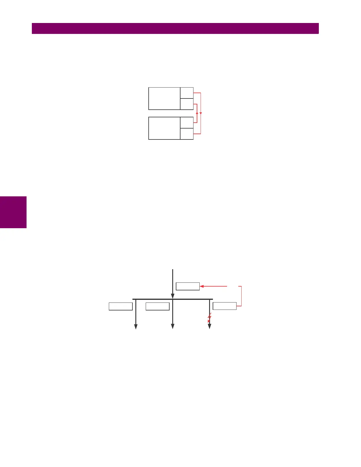
Example 2: Interlocking busbar protection
A simple interlocking busbar protection scheme could be accomplished by sending a blocking signal from downstream
devices, say 2, 3, and 4, to the upstream device that monitors a single incomer of the busbar, as shown below.
Figure 5–19: SAMPLE INTERLOCKING BUSBAR PROTECTION SCHEME
For increased reliability, a dual-ring configuration (shown below) is recommended for this application.
842711A1.CDR
UR IED 1
TX1
RX1
UR IED 2
TX1
RX1
842712A1.CDR
UR IED 1
UR IED 2
UR IED 4
UR IED 3
BLOCK