5-96 C60 Breaker Protection System GE Multilin
5.2 PRODUCT SETUP 5 SETTINGS
5
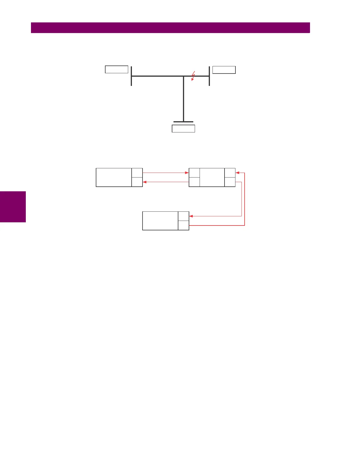
Example 3: Pilot-Aided Schemes
Consider the three-terminal line protection application shown below:
Figure 5–21: THREE-TERMINAL LINE APPLICATION
A permissive pilot-aided scheme could be implemented in a two-ring configuration as shown below (IEDs 1 and 2 constitute
a first ring, while IEDs 2 and 3 constitute a second ring):
Figure 5–22: SINGLE-CHANNEL OPEN LOOP CONFIGURATION
In the above application, the following settings should be applied. For UR-series IED 1:
DIRECT OUTPUT DEVICE ID: “1”
DIRECT I/O CH1 RING CONFIGURATION: “Yes”
DIRECT I/O CH2 RING CONFIGURATION: “Yes”
For UR-series IED 2:
DIRECT OUTPUT DEVICE ID: “2”
DIRECT I/O CH1 RING CONFIGURATION: “Yes”
DIRECT I/O CH2 RING CONFIGURATION: “Yes”
For UR-series IED 3:
DIRECT OUTPUT DEVICE ID: “3”
DIRECT I/O CH1 RING CONFIGURATION: “Yes”
DIRECT I/O CH2 RING CONFIGURATION: “Yes”
In this configuration the following delivery times are expected (at 128 kbps):
IED 1 to IED 2: 0.2 of power system cycle;
IED 1 to IED 3: 0.5 of power system cycle;
IED 2 to IED 3: 0.2 of power system cycle.
In the above scheme, IEDs 1 and 3 do not communicate directly. IED 2 must be configured to forward the messages as
explained in the Inputs and Outputs section. A blocking pilot-aided scheme should be implemented with more security and,
ideally, faster message delivery time. This is accomplished using a dual-ring configuration as shown here.
842713A1.CDR
UR IED 1
UR IED 2
UR IED 3
842714A1.CDR
UR IED 1
TX1
RX1
UR IED 2
RX2
TX2
RX1
TX1
UR IED 3
RX1
TX1