GE Multilin C60 Breaker Protection System 5-123
5 SETTINGS 5.4 SYSTEM SETUP
5
Synchrophasor data as measured and calculated by phasor measurement units (PMUs) is used to assess the condition of
the electrical power network. The IEEE C37.118 standards define synchrophasors and related message formats to transmit
synchrophasor data. Synchrophasor streaming via IEEE C37.118 has proven to work but the desire to have a communica-
tion mechanism that is compliant with the concept of IEC 61850 has led to the development of IEC 61850-90-5. The IEC
61850-90-5 standard defines the packet structure for multicast routing of streamed Sampled Value (SV) known as R-SV.
Firmware versions 7.0 and above have a 90-5 based R-SV implementation equivalent in structure and configuration to that
of the existing IEEE C37.118 implementation of firmware version 6.0, that is, synchrophasor data at rates up to 60 Hz for
metering and 120 Hz for protection class synchrophasors. The following two figures depict the general data flow for the
generation of synchrophasor data for IEC 61850-90-5. In the first figure, when IEC 61850-90-5 is selected all real and vir-
tual sources are available for the IEC 61850-90-5 PMUs.
The number of PMUs and aggregators vary by product, as outlined in the table.
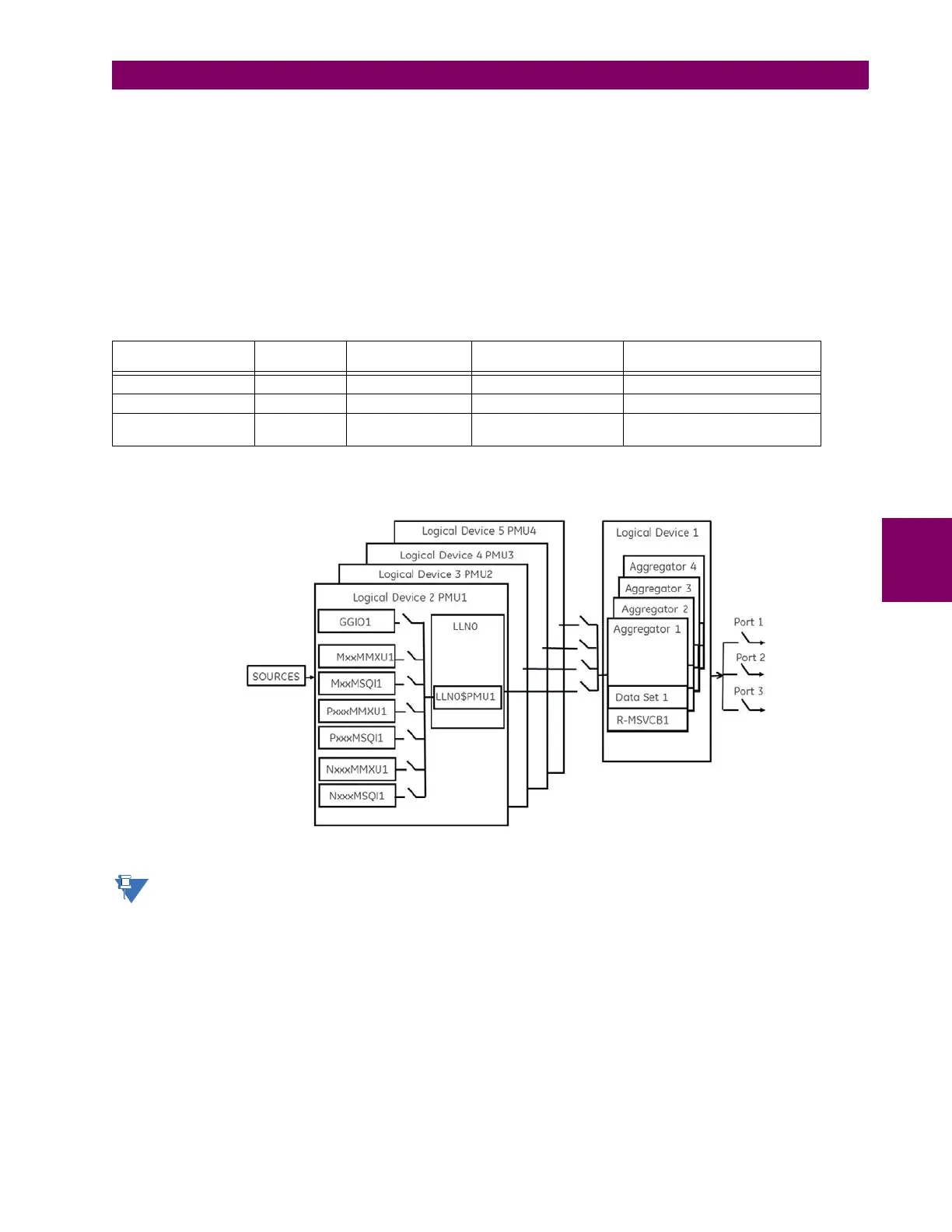
The figure shows an example of an N60 using four Logical Device PMUs (Logical Device 2 through 5) and four aggrega-
tors. The control blocks for the aggregators are located in LD1. A 64 char LDName setting is provided.
Figure 5–42: N60 EXAMPLE FOR FOUR LOGICAL DEVICE PMUS
Precise time input to the relay from the international time standard, via either IRIG-B or PTP, is vital for correct syn-
chrophasor measurement and reporting. For IRIG-B, a DC level shift IRIG-B receiver must be used for the phasor
measurement unit to output proper synchrophasor values.
Table 5–14: IMPLEMENTATION BY MODEL NUMBER
MODEL NUMBER OF
PMUS
NUMBER OF
AGGREGATORS
NUMBER OF ANALOG
INPUTS
COMMENT
N60 6 4 16 1, 2, 4, or 6 PMUs can be used
C60 2 2 16
D60, F60, G60, L30,
L90, T60
11 16