5-244 C60 Breaker Protection System GE Multilin
5.7 CONTROL ELEMENTS 5 SETTINGS
5
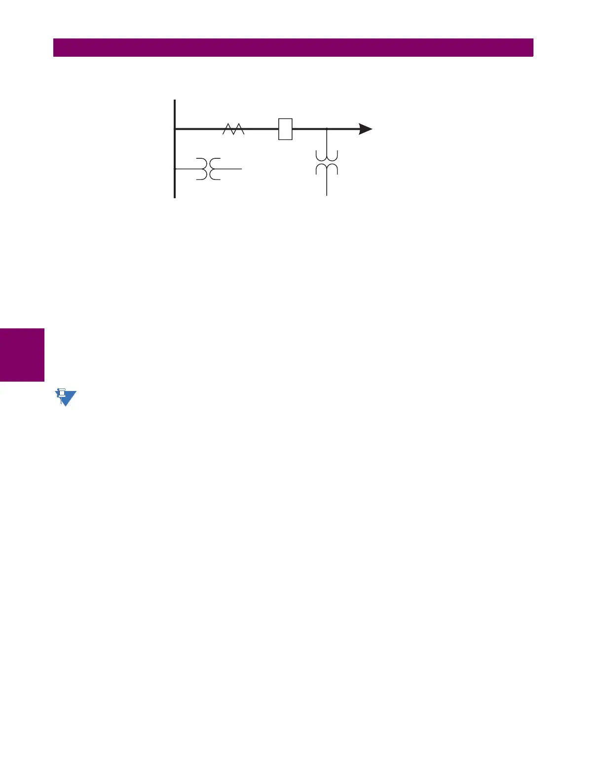
Consider the following configuration:
The source 1 (SRC1) phase currents are CTs and phase voltages are bus VTs. The source 2 (SRC2) phase voltages are
line VTs. Contact input 1 is set as the breaker 52a contact (optional).
The conditions prior to flashover detection are:
1. ΔVA is greater than pickup
2. IA, IB, IC = 0; no current flows through the breaker
3. 52a status = 0 (optional)
The conditions at flashover detection are:
1. ΔVA is less than pickup
2. VAg, VBg, or VCg is lower than the pickup setting
3. IA, IB, or IC is greater than the pickup current flowing through the breaker
4. 52a status = 0 (optional)
The element is operational only when phase-to-ground voltages are connected to relay terminals. The flashover
element will not operate if delta voltages are applied.
The breaker flashover settings are described below.
• BRK 1 FLSHOVR SIDE 1 SRC: This setting specifies a signal source used to provide three-phase voltages and three-
phase currents from one side of the current breaker. The source selected as a setting and must be configured with
breaker phase voltages and currents, even if only three (3) VTs are available across the breaker.
• BRK 1 FLSHOVR SIDE 2 SRC: This setting specifies a signal source used to provide another set of three phase volt-
ages whenever six (6) VTs are available across the breaker.
• BRK 1 STATUS CLSD A to BRK 1 STATUS CLSD C: These settings specify FlexLogic operands to indicate the open
status of the breaker. A separate FlexLogic operand can be selected to detect individual breaker pole status and pro-
vide flashover detection. The recommended setting is 52a breaker contact or another operand defining the breaker
poles open status.
• BRK 1 FLSHOVR V PKP: This setting specifies a pickup level for the phase voltages from both sides of the breaker. If
six VTs are available, opening the breaker leads to two possible combinations – live voltages from only one side of the
breaker, or live voltages from both sides of the breaker. Either case will set the scheme ready for flashover detection
upon detection of voltage above the selected value. Set
BRK FLSHOVR V PKP to 85 to 90% of the nominal voltage.
• BRK 1 FLSHOVR DIFF V PKP: This setting specifies a pickup level for the phase voltage difference when two VTs per
phase are available across the breaker. The pickup voltage difference should be below the monitored voltage differ-
ence when close or open breaker resistors are left in service. The setting is selected as primary volts difference
between the sources.
• BRK 1 FLSHOVR AMP PKP: This setting specifies the normal load current which can flow through the breaker.
Depending on the flashover protection application, the flashover current can vary from levels of the charging current
when the line is de-energized (all line breakers open), to well above the maximum line (feeder) load (line/feeder con-
nected to load).
842745A1.CDR
VTs
VTs
Line/Feeder
BreakerCTs
Bus