5-266 C60 Breaker Protection System GE Multilin
5.8 INPUTS AND OUTPUTS 5 SETTINGS
5
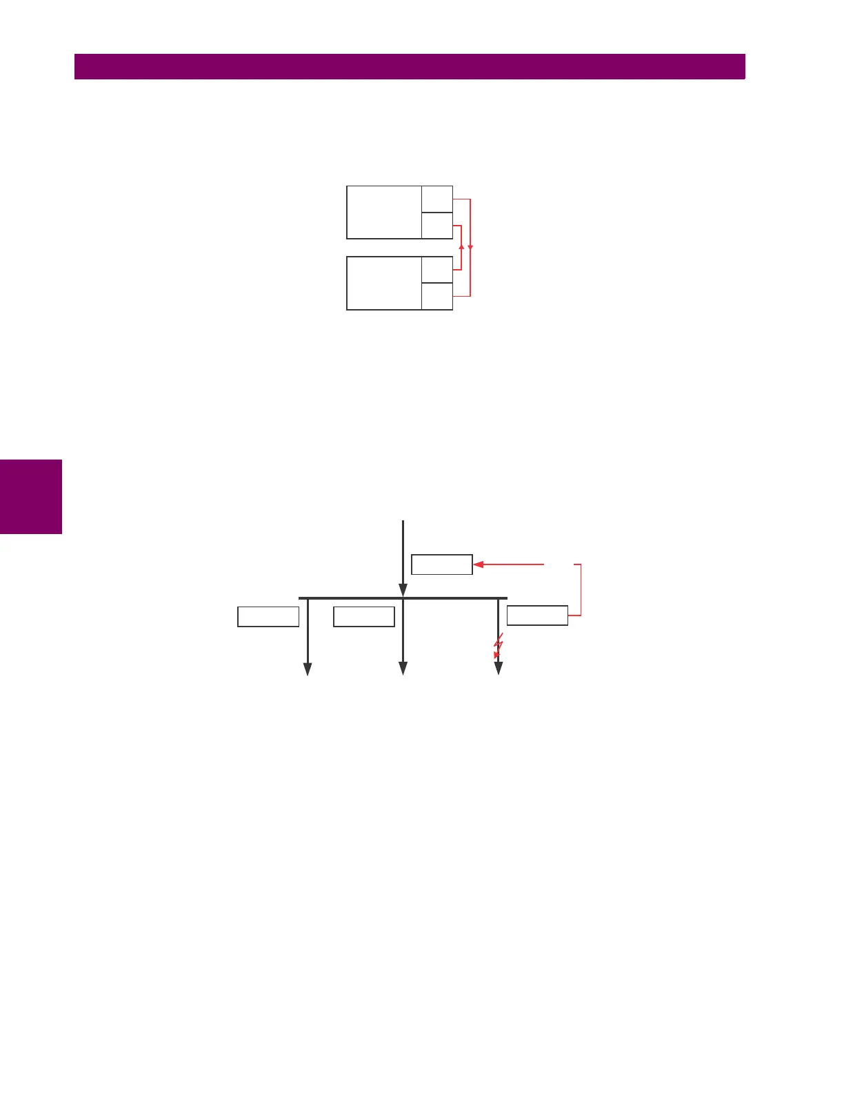
Example 1: Extending input/output capabilities of a C60 relay
Consider an application that requires additional quantities of contact inputs or output contacts or lines of programmable
logic that exceed the capabilities of a single UR-series chassis. The problem is solved by adding an extra UR-series IED,
such as the C30, to satisfy the additional inputs/outputs and programmable logic requirements. The two IEDs are con-
nected via single-channel digital communication cards as shown below.
Figure 5–119: INPUT AND OUTPUT EXTENSION VIA DIRECT INPUTS AND OUTPUTS
Assume contact input 1 from UR IED 2 is to be used by UR IED 1. The following settings should be applied (Direct Input 5
and bit number 12 are used, as an example):
The Cont Ip 1 On operand of UR IED 2 is now available in UR IED 1 as DIRECT INPUT 5 ON.
Example 2: Interlocking busbar protection
A simple interlocking busbar protection scheme can be accomplished by sending a blocking signal from downstream
devices, say 2, 3 and 4, to the upstream device that monitors a single incomer of the busbar, as shown in the figure below.
Figure 5–120: SAMPLE INTERLOCKING BUSBAR PROTECTION SCHEME
Assume that Phase Instantaneous Overcurrent 1 is used by Devices 2, 3, and 4 to block Device 1. If not blocked, Device 1
would trip the bus upon detecting a fault and applying a short coordination time delay.
The following settings should be applied (assume Bit 3 is used by all 3 devices to send the blocking signal and Direct Inputs
7, 8, and 9 are used by the receiving device to monitor the three blocking signals):
UR IED 2:
DIRECT OUT 3 OPERAND: "PHASE IOC1 OP"
UR IED 3:
DIRECT OUT 3 OPERAND: "PHASE IOC1 OP"
UR IED 4: DIRECT OUT 3 OPERAND: "PHASE IOC1 OP"
UR IED 1:
DIRECT INPUT 7 DEVICE ID: "2"
DIRECT INPUT 7 BIT NUMBER: "3"
DIRECT INPUT 7 DEFAULT STATE: select "On" for security, select "Off" for dependability
DIRECT INPUT 8 DEVICE ID: "3"
DIRECT INPUT 8 BIT NUMBER: "3"
DIRECT INPUT 8 DEFAULT STATE: select "On" for security, select "Off" for dependability
UR IED 1:
DIRECT INPUT 5 DEVICE ID = “2”
DIRECT INPUT 5 BIT NUMBER = “12”
UR IED 2: DIRECT OUT 12 OPERAND = “Cont Ip 1 On”
UR IED 1
TX1
RX1
UR IED 2
TX1
RX1
842712A1.CDR
UR IED 1
UR IED 2
UR IED 4
UR IED 3
BLOCK